Host Interface 38 (114)
3.6.2 Pin Usage in Serial Mode
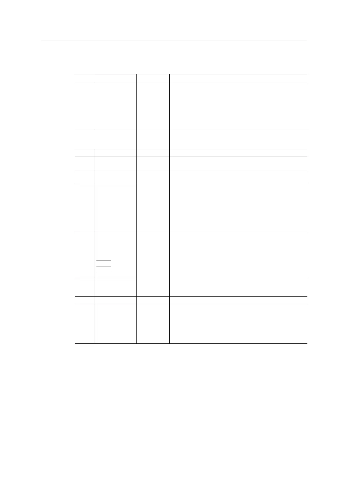
Presented below is an overview of all pins except GND and 3V3
Pin Signal Name Pin Type Description/Comments
49
24
48
23
47
22
46
21
DIP1_0
DIP1_1
DIP1_2
DIP1_3
DIP1_4
DIP1_5
DIP1_6
DIP1_7
I
I
I
I
I
I
I
I
DIP switch. Usage defined by application.
Readable through attribute #14 (Switch status) in Anybus Object,
instance #1.
Connect to GND if not used.
45
20
44
(not used) I
I
O,I
Connect to GND
19 (not used) I Connect to 3V3.
43 ASI RX I See Black Channel/Safety Module, p. 41
If not used, connect to 3V3.
18 ASI TX O See Black Channel/Safety Module, p. 41
If not used, leave unconnected.
14
39
15
40
16
41
17
42
DIP2_0
DIP2_1
DIP2_2
DIP2_3
DIP2_4
DIP2_5
DIP2_6
DIP2_7
I
I
I
I
I
I
I
I
DIP switch. Usage defined by application.
Readable through attribute #14 (Switch status) in Anybus Object,
instance #1.
Connect to GND if not used.
4
29
5
30
6
31
7
32
LED1B
LED1A
LED2B
LED2A
LED3B
LED3A
LED4B
LED4A
O
O
O
O
OD
OD
O
O
LED interface. Gives access to LED indications. For more
information, LED Interface / D8–D15 (Data Bus), p. 13.
When not used, LED1A, LED1B, LED2A, LED2B, LED4A and
LED4B can be left unconnected.
LED3A and LED3B are open-drain outputs and should, if not
used, be pulled either to GND or to 3V3, depending on application.
34
33
10
(not used) I
I
I
Connect to 3V3.
9 (not used) O Leave unconnected
28 RX I Receive Input
• Direction: Host application -> Anybus CompactCom
• Idle state = High
Connect to 3V3 if not used.
Anybus
®
CompactCom
™
M40 Hardware Design Guide HMSI-216-126 EN 2.6