EasyManuals Logo

Anybus CompactCom M40 User Manual

Anybus CompactCom M40
116 pages
To Next Page IconTo Next Page
To Previous Page IconTo Previous Page
Page #96 background imageLoading...
Page #96 background image
Appendix D: Mechanical Specification 94 (114)
D.6.2 Host Connector Pin Numbering
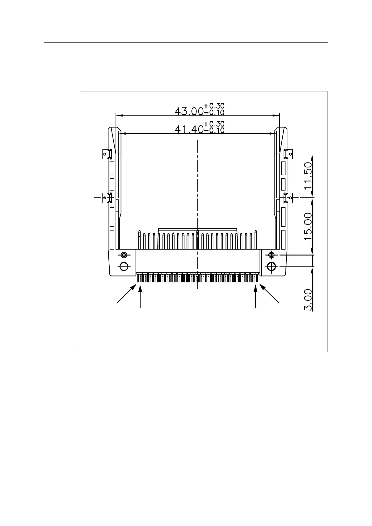
The surface mounted pins of the HMS compact flash connector are numbered from left to right
(see figure below), corresponding to pin numbers 1, 26, 2, 27...... 25, 50 of the host interface
connector.
Bottom view of the host connector
1
26
25
50
Fig. 48
Anybus
®
CompactCom
M40 Hardware Design Guide HMSI-216-126 EN 2.6

Table of Contents

Questions and Answers:

Question and Answer IconNeed help?

Do you have a question about the Anybus CompactCom M40 and is the answer not in the manual?

Anybus CompactCom M40 Specifications

General IconGeneral
BrandAnybus
ModelCompactCom M40
CategoryConference System
LanguageEnglish