Do you have a question about the Applanix LVX and is the answer not in the manual?
Specifies performance details for the LVX product, including GNSS tracking capabilities and proprietary IMU technology.
Details the key features of the LVX, including its dual antenna GNSS module and Trimble Maxwell technology.
Describes the LVX unit's IP67 sealed housing and its mechanical dimensions, referencing Figure 2.
Details the process for installing the Distance Measuring Indicator (DMI) on a vehicle's rear wheel.
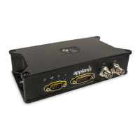
Covers the LVX connectors, including GNSS antenna, power/IO, and DMI connectors, and their types.
Explains the function and status indications of the four LEDs on the LVX front panel.
Guides users on how to connect to the LVX via a web browser using its static IP address.
Describes the layout of the LVX web user interface, including system name, serial number, and language selection.
Explains how to view product information, system name, serial number, and software/hardware versions.
Details how to log raw data for post-processing using internal memory or external USB devices.
Explains the 1PPS time strobe output and associated ASCII time tag message format.
Covers various system configuration settings, including antenna, tracking, position, and general configurations.
Instructions for configuring GNSS antennas, including selecting 'Unknown External' and 'Antenna Phase Center'.
Allows users to select tracking elevation mask angle and satellite systems, recommending default settings.
Guides on selecting the correct Dynamic Model (Mapping vehicle or Off-road vehicle) for performance.
Details settings for discrete I/O signals, including Event 1 & 2 inputs and 1 PPS output.
Covers entering relative position and orientation of LVX with vehicle and GNSS antennas.
Defines the IMU Body frame as the right-hand orthogonal coordinate system measured by the inertial sensors.
Defines the Reference Body frame as a right-hand orthogonal coordinate system at a sensor's reference center.
Defines the Vehicle Body Frame as a right-hand orthogonal system referenced to the vehicle's vertical and horizontal planes.
Defines the DMI Frame with its origin at the Instrumented Wheel's point of contact with the road.
Explains lever arm definitions for IMU, GNSS, and DMI relative to reference frames.
Defines mounting angles as physical angular offsets between body frames, related to Tait-Bryan sequence.
Explains how to calculate the DMI scale factor using pulses per wheel revolution and wheel diameter.
Details output message selection for specific ports, allowing configuration of NMEA and other message types.
Covers precise positioning product supporting differential correction inputs like CMR, CMR+, RTCM for real-time accuracy.
Explains how to configure static IP address, subnet, gateway, and DNS server for the LVX Ethernet connection.
Guides on performing firmware upgrades via the web interface using the 'Choose File' and 'Install New Firmware' options.
Details how to measure the baseline vector and its accuracy for GAMS calibration.
Explains the GAMS Calibration feature using 'Dynamic Heading Alignment' to estimate baseline vectors.
Steps to set up GAMS calibration, including enabling GAMS and configuring GNSS Lever Arm.
Procedure for calibrating the baseline vector for land vehicles, involving static and dynamic maneuvers.
Describes methods for saving calibrated baseline vector values: Auto-copy or Manual copy.
Explains how the system uses GNSS antennas and baseline parameters for heading aiding.
Details the ASCII message selection, focusing on NMEA messages and their configuration.
Describes the PASHR message, providing real-time attitude and heading information.
Explains binary output using Trimble GSOF message format and message selection via web interface.
Defines integer data types (CHAR, SHORT, LONG) used by the LVX, specifying byte order.
Details the GSOF 49 message format for INS integrated navigation solution, including record type and GPS data.
Details the GSOF 50 message format for INS integrated navigation solution RMS values.
Details the GSOF 51 message format for event marker information, including event port and time.
Details GSOF 59 and 60 message formats for event triggered navigation information.
Guides on setting up the LVX for RTK using its built-in NTRIP client, including network configuration.
Explains how to use RTX corrections via the internet, referencing Section 6.1 setup for NTRIP client.
Describes using external NTRIP client software for RTK setup with the LVX.
| Impedance | 50 Ω |
|---|---|
| Connector Type | TNC |
| Operating Temperature | -40 °C to +85 °C |
| Ingress Protection | IP67 |
| Frequency Bands | L1/L2/L5 GPS, GLONASS, BeiDou, Galileo, QZSS, SBAS |
| Noise Figure | 2.0 dB |
| VSWR | 1.5:1 |