32
THE INFORMATION CONTAINED HEREIN IS PROPRIETARY TO APPLANIX CORPORATION. RELEASE TO THIRD PARTIES OF THIS PUBLICATION OR OF
INFORMATION CONTAINED HEREIN IS PROHIBITED WITHOUT THE PRIOR WRITTEN CONSENT OF APPLANIX CORPORATION. APPLANIX RESERVES THE
RIGHT TO CHANGE THE SPECIFICATIONS AND INFORMATION IN THIS DOCUMENT WITHOUT NOTICE. A RECORD OF THE CHANGES MADE TO THIS
DOCUMENT IS CONTAINED IN THE REVISION HISTORY SHEET. COPYRIGHT © APPLANIX CORPORATION, 2021ALL RIGHTS RESERVED. NO PART OF
THIS PUBLICATION MAY BE REPRODUCED, STORED IN A RETRIEVAL SYSTEM OR TRANSMITTED IN ANY FORM OR BY ANY MEANS WITHOUT THE
PRIOR WRITTEN CONSENT OF APPLANIX CORPORATION.
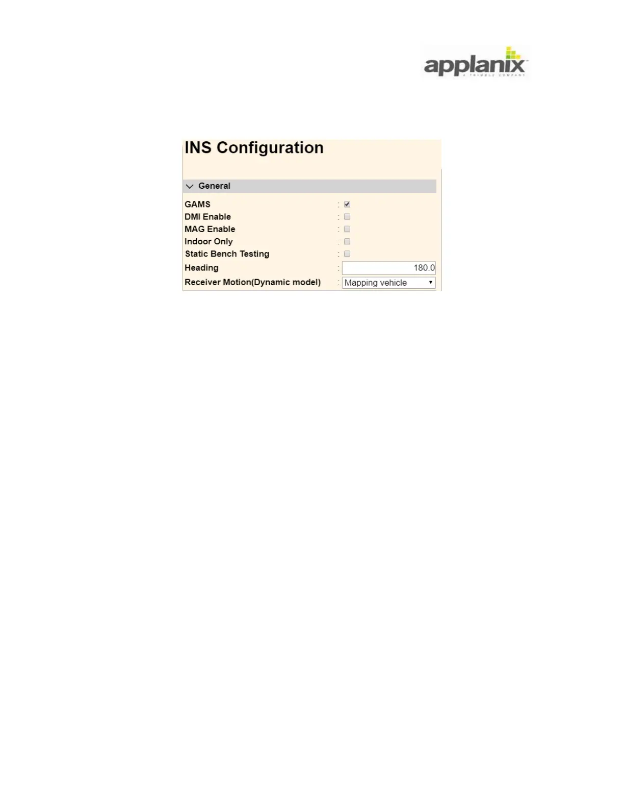
Mapping vehicle: raw observables to be used in real-time and for post-processing
Automotive: raw observables to be used in real-time only
Off-road vehicle: nonholonomic constraint not in use
*The nonholonomic constraint (which is a constraint on the possible velocities of the
vehicle) is in use for the Mapping vehicle and Automotive dynamic models, where the
plane formed through the rear-wheel axis is constrained.
It is also recommended that the MAG Enable option be unchecked.
4.6.6. IMU Body Frame Definition:
The IMU Body frame is the right-hand orthogonal coordinate system that is measured by
the inertial sensors on the LVX. The origin of the IMU body frame is offset from the
target on top of LVX by the dimensions listed on the target label (see Figure 32).
4.6.7. Reference Body Frame Definition:
The Reference Body frame is defined as the right-hand orthogonal coordinate system
with its origin at the centre of a location to which a related sensor is referenced. For
example, using the LVX mounted on a scanner, the origin of the reference body frame is
at the origin of the scanner measurements, and the x, y, and z are the orthogonal axis of
the scanner frame.
All measurements output by the LVX system are at the Reference frame origin and
aligned to the Reference frame axis.