31
THE INFORMATION CONTAINED HEREIN IS PROPRIETARY TO APPLANIX CORPORATION. RELEASE TO THIRD PARTIES OF THIS PUBLICATION OR OF
INFORMATION CONTAINED HEREIN IS PROHIBITED WITHOUT THE PRIOR WRITTEN CONSENT OF APPLANIX CORPORATION. APPLANIX RESERVES THE
RIGHT TO CHANGE THE SPECIFICATIONS AND INFORMATION IN THIS DOCUMENT WITHOUT NOTICE. A RECORD OF THE CHANGES MADE TO THIS
DOCUMENT IS CONTAINED IN THE REVISION HISTORY SHEET. COPYRIGHT © APPLANIX CORPORATION, 2021ALL RIGHTS RESERVED. NO PART OF
THIS PUBLICATION MAY BE REPRODUCED, STORED IN A RETRIEVAL SYSTEM OR TRANSMITTED IN ANY FORM OR BY ANY MEANS WITHOUT THE
PRIOR WRITTEN CONSENT OF APPLANIX CORPORATION.
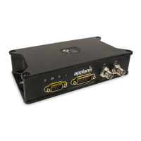
4.6.5. INS Configuration:
Once the LVX and antennas are installed on the vehicle, the relative position and
orientation of the LVX with respect to the vehicle and GNSS antennas must be entered.
Two types of measurements are required:
1. Lever arms - vector displacement between two body frames
2. Mounting angles - differences in orientation between two body frames
The correct measurements must be entered into the software for the system to function
properly. Failure to do so will result in degraded performance.
New values must be entered after the location of any component has changed, or the first
time the system is powered-on after a new installation. See the Figure 37 for more
information on storing installation parameters in the LVX.
Accurate measurements of the mounting parameters are necessary to ensure optimum
performance of the system. Six sets of parameters are required to be measured and input
into the system before the LVX can operate. These parameters are as follows:
Reference frame origin to IMU lever arm
Reference frame origin to Primary GNSS antenna lever arm
IMU body frame with respect to reference body frame mounting angles
Reference frame with respect to vehicle body frame mounting angles
Primary GNSS antenna to Secondary GNSS antenna baseline vector
DMI/Rear Wheel lever arm
DMI Scale Factor
The accuracy requirements of these measurements are important. Mounting angles
(known as misalignment or boresight angles) are measured to the accuracy expected from
the LVX system. For example, if vehicle roll has a required accuracy of 0.05 degrees,
then the IMU body frame with respect to the reference body frame mounting angles must
be measured and entered to better than 0.05 degrees accuracy. If the accuracy of the
measurements does not meet these requirements, a constant angular offset will be present
in the output and the error may manifest itself as a lever arm error.
Precise mounting angle measurements are usually performed by lab calibration or a
boresighting mission. Contact Applanix Customer Support for more information on
measuring mounting angles.
The Applanix Position and Orientation System Post-Processing Package (POSPac) post-
processing software can be used to help refine the installation parameter estimates.
In addition to the lever arm and mounting angles setup under INS Configuration, the
appropriate Receiver Motion (Dynamic model) is indicated, where the options available
include: