2
THE INFORMATION CONTAINED HEREIN IS PROPRIETARY TO APPLANIX CORPORATION. RELEASE TO THIRD PARTIES OF THIS PUBLICATION OR OF
INFORMATION CONTAINED HEREIN IS PROHIBITED WITHOUT THE PRIOR WRITTEN CONSENT OF APPLANIX CORPORATION. APPLANIX RESERVES THE
RIGHT TO CHANGE THE SPECIFICATIONS AND INFORMATION IN THIS DOCUMENT WITHOUT NOTICE. A RECORD OF THE CHANGES MADE TO THIS
DOCUMENT IS CONTAINED IN THE REVISION HISTORY SHEET. COPYRIGHT © APPLANIX CORPORATION, 2021ALL RIGHTS RESERVED. NO PART OF
THIS PUBLICATION MAY BE REPRODUCED, STORED IN A RETRIEVAL SYSTEM OR TRANSMITTED IN ANY FORM OR BY ANY MEANS WITHOUT THE
PRIOR WRITTEN CONSENT OF APPLANIX CORPORATION.
Galileo: E1, E5A, E5B, E5AltBOC
IRNSS: L5
QZSS: L1 C/A, L1 SAIF, L2C, L5, LEX
SBAS: L1 C/A, L5
Proprietary Trimble MEMS IMU technology with an update rate of 200Hz, calibrated to
meet the needs of mobile mapping applications.
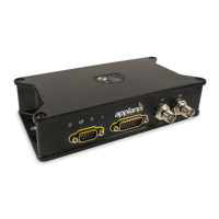
Interfaces:
1 USB 2.0 device port
1 physical LAN Ethernet port:
o Supports links to 10BaseT/100BaseT auto-negotiate networks
2 x RS232 Serial ports (one Tx/Rx and one Tx/Rx/CTS/RTS)
1 Pulse Per Second Output
2 x Event Marker Input Support
Supported Network protocols:
HTTP (web GUI)
NMEA, GSOF, CMR over TCP/IP or UDP
Supported differential corrections:
CMR, CMR+™, sCMRx, RTCM 2.1, 2.2, 2.3, 3.0, 3.1, 3.2.
Navigation outputs:
ASCII: PPS Time Mark,NMEA-0183 (GBS; GGA; GLL; GNS; GRS; GSA;
GST; GSV; HDT; LLQ; AVR; GDP; DTM;BPQ; GGK; PJK; PJT; VGK; VHD;
RMC; ROT; VTG; ZDA).
Binary: Trimble GSOF.
Control software:
HTML Web browser (Google Chrome, Internet Explorer®, Mozilla Firefox,
Apple Safari, Opera)
3. LVX Hardware Description and Interface
3.1. Mechanical
The LVX is an IP67 sealed housing with mechanical dimensions as shown in Figure 2.
The location of the center of navigation, or sensing center of the IMU, is shown in Figure
3 along with the associated offsets from the axis target on top of the enclosure.