33
THE INFORMATION CONTAINED HEREIN IS PROPRIETARY TO APPLANIX CORPORATION. RELEASE TO THIRD PARTIES OF THIS PUBLICATION OR OF
INFORMATION CONTAINED HEREIN IS PROHIBITED WITHOUT THE PRIOR WRITTEN CONSENT OF APPLANIX CORPORATION. APPLANIX RESERVES THE
RIGHT TO CHANGE THE SPECIFICATIONS AND INFORMATION IN THIS DOCUMENT WITHOUT NOTICE. A RECORD OF THE CHANGES MADE TO THIS
DOCUMENT IS CONTAINED IN THE REVISION HISTORY SHEET. COPYRIGHT © APPLANIX CORPORATION, 2021ALL RIGHTS RESERVED. NO PART OF
THIS PUBLICATION MAY BE REPRODUCED, STORED IN A RETRIEVAL SYSTEM OR TRANSMITTED IN ANY FORM OR BY ANY MEANS WITHOUT THE
PRIOR WRITTEN CONSENT OF APPLANIX CORPORATION.
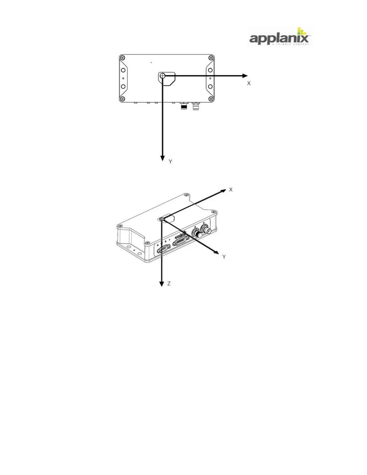
Figure 32: IMU Body Frame Definition
4.6.8. Vehicle Body Frame:
The Vehicle Body Frame is defined as the right-hand orthogonal coordinate system with
its origin at the vehicle’s centreline. Its three axis are referenced to the vehicle’s vertical
and horizontal planes where the:
X-axis is parallel to the horizontal plane and extends towards the front - called the
vehicle longitudinal axis any rotation about this axis is called ‘roll’.
Y-axis is parallel to the horizontal plane and extends towards the starboard (right)
side - called the vehicle lateral axis, any rotation about this axis is called ‘pitch’.