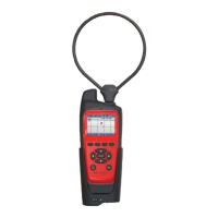
21
as defined in the QAM Snare Manager program.
While cradled, the detector displays the leak level as measured at the corresponding
RF antenna installed on the roof of the vehicle. Every second, data on detected leaks,
delay information on detected leaks, GPS coordinates of the vehicle, and measured LTE
signal level is transmitted to the QAM Snare Server. If a
leak is detected, the Server will calculate the GPS
coordinates of the leak using a sophisticated Time
Difference of Arrival (TDOA) algorithm and update the leak
database with the leak location and the calculated 10 ft.
leak level. This same information on the calculated leak
level is transmitted back to the field detector – which uses
this calculated level information for the audio alarms that
provide technician feedback when leaks are detected. Alarming on calculated actual
leak level instead of simply detected level is a big time saver by if automatic fix rules
are established in that the user immediately knows when they are driving by large leak.
The necessity of driving back to a leak is eliminated. The two alarms thresholds for
audio indication are configured through settings.
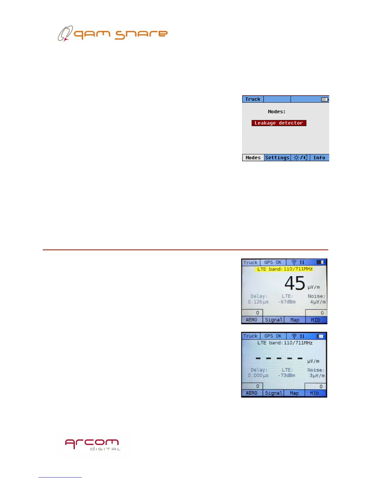
Leak level display screen
The default leakage detector screen will prominently
display the detected level in the selected band. The
screens will appear slightly different depending upon if
analog aeronautical band detection was selected, and
depending upon configured number of channels. When no
leakage is detected on a channel, a series of dashes will be
displayed, and will blink every second as an indication that
data is being received from the server. The channel
currently being displayed is written prominently above the
leak level indicator. As leaks are detected that are above
the alarm thresholds, the color of the band indicator will
switch to yellow or red corresponding to low or high level
alarms. Detected leaks in the other two bands (if selected
for detection) are also displayed in the bottom right and
left portion of the screen. To switch the main display to
 Loading...