HARDWARE INSTALLATION
48
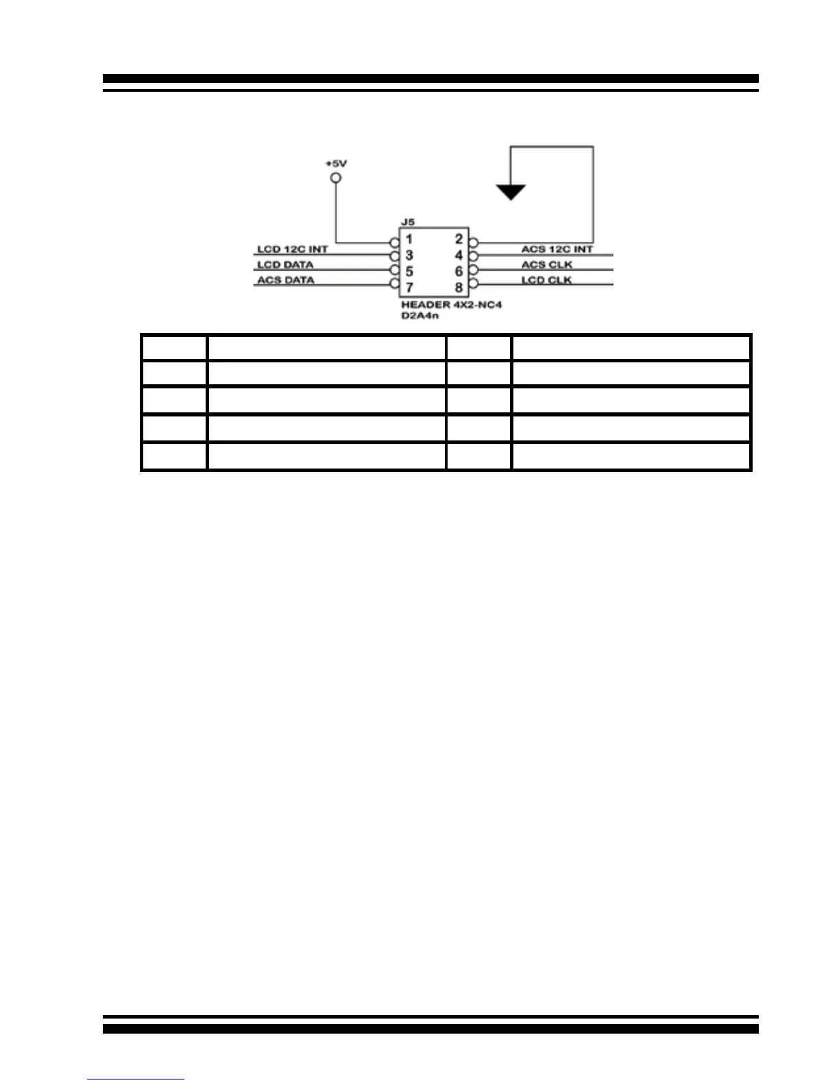
PIN Description PIN Description
1 power (+5V) 2 GND
3 LCD Module Interrupt 4 Fault/Activity Interrupt
5 LCD Module Serial Data 6 Fault/Activity clock
7 Fault/Activity Serial Data 8 LCD Module clock
The following is the I
2
C signal name description for LCD & Fault/Ac-
tivity LED.
D: SGPIO Connector
The preferred I/O connector for server backplanes is the Min SAS
4i internal serial-attachment connector. This connector has eight
signal pins to support four SATA drives and six pins for the SGPIO
(Serial General Purpose Input/Output) side-band signals. The
SGPIO bus is used for efcient LED management and for sens-
ing drive Locate status. See SFF 8485 for the specication of the
SGPIO bus.
The number of drives supported can be increased, by a factor of
four, by adding similar backplane to maximum of 24 drives (6
backplanes)
LED Management: The backplane may contain LEDs to indicate
drive status. Light from the LEDs could be transmitted to the out-
side of the server by using light pipes mounted on the SAS drive
tray. A small microcontroller on the backplane, connected via the
SGPIO bus to a ARC-1230ML/1260ML/1280ML SATA RAID con-
troller, could control the LEDs. Activity: blinking 5 Times/Second
Fault: solid illuminated
Drive Locate Circuitry: The locate of a drive may be detected by
sensing the voltage level of one of the pre-charge pins before and