Subject to change · V 2.02.20 · EN
Page 15
www.argo-hytos.com
7. Assembly
7.1 Operating site
Please follow these instructions when determining the mounting location:
› Connect the particle monitor in bypass flow to a pressure line.
› The flow direction is arbitrary.
› At the connection point there should preferably be constant pressure conditions.
The pressure may vary, but there must not be pressure peaks or strong fluctuations.
› The volume flow must be constant and be between 50 and 400 ml/min.
› A flow control or pressure reduction must always be installed downstream of the particle monitor, since these can generate
turbulences or air bubbles which cause measurement errors.
› If a pump is needed to generate the required flow, this should be a low pulsation pump which should be installed in the pressure
line since negative pressure on the suction side can lead to air bubbles which would cause measurement errors.
› If air bubbles occur in the system, a calming section in form of a hose of approx. 2 meters should be installed ahead of the sensor.
7.2 Hydraulic connection
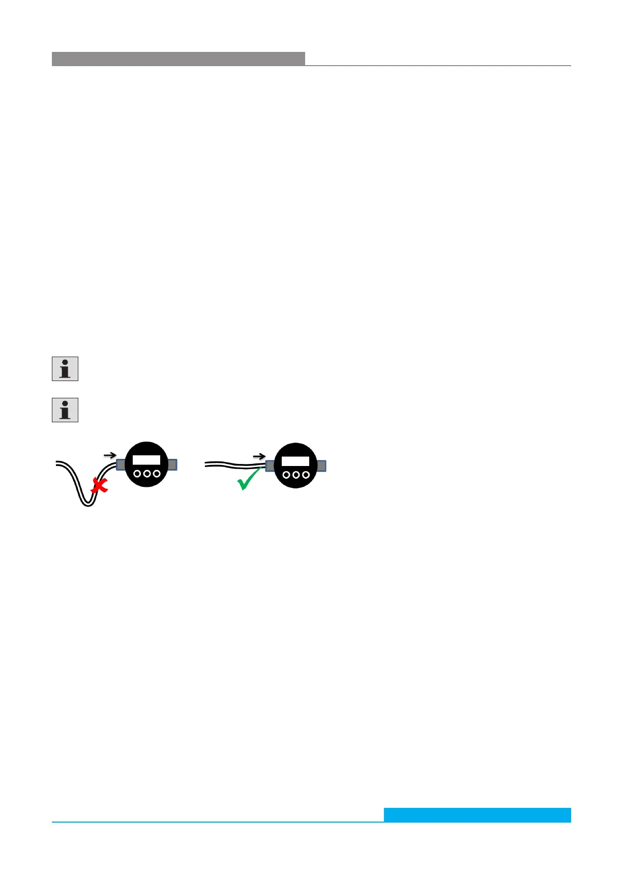
The sensor has two ¼“-screw connections and is delivered from the factory with screwed Minimess connections. The system
pressure generates the required flow rate and needs to be throttled after the device. The flow direction can be chosen freely.
To be able to read the display and use the keyboard, the device should be installed at an accessible position. With the length of the
hoses, the risk of settling of larger particles increases. Furthermore, especially at higher viscosities and when using Minimess hoses, it
must be ensured that the pressure is sufficiently high to generate a flow between 50 and 400 ml/min.
The Minimess connections can be exchanged by other connectors.
A maximum tightening torque of 25 Nm shall not be exceeded.
While exchanging the connection couplings, no dirt, chips or other contaminations shall enter the interior of the device.
Fig. 6: Hydraulic connection, avoid blind holes in the supply line
The device should be installed at a relevant measurement location in the hydraulic circuit where constant pressure conditions exist.
The pressure may vary, but it must not show any peaks or strong fluctuations during the measurement.


 To Next Page