Subject to change · V 2.02.20 · EN
Page 35
www.argo-hytos.com
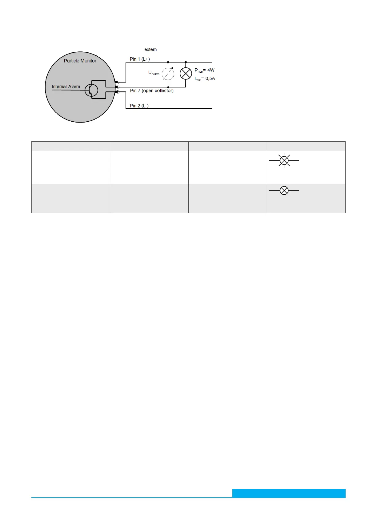
14.2.2 Option 2
Fig. 23: Connection diagram switching output option 2
Table 20: Switching behavior of switching output option 2
Alarm Statement Voltage measurement When connecting a consumer
Available (true)
The internal transistor
connects pin 7 to pin 2. The
voltage is measured against L-.
U
Alarm
= L+
P
max
= 4 W
I
max
= 0,5A
Missing (false) Pin 7 is not connected
(floating).
U
Alarm
= L- = 0V
P
max
= 4 W
I
max
= 0,5A