Subject to change · V 2.02.20 · EN
Page 34
www.argo-hytos.com
14. Switching inputs and outputs
14.1 Digital input
The digital input is needed for the measuring mode: Digital I/O. To start and stop a measurement, pin 5 has to be set either to
L- or L+. For further information see Chapter 12.2.2 Digital I/O.
14.2 Switching output
The appearance of an alarm can be detected next to the red LED and the warning triangle on the display on the alarm output at pin
7. See Chapter 12.3 "Configuration alarm".
Two options are available.
Pin 7 is not a switch in the sense of a turnkey.
Depending on the state of alarm, pin 7 is on the ground (L-) or it is not connected (floating).
14.2.1 Option 1
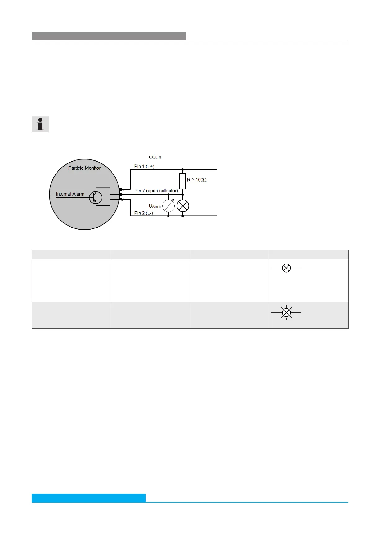
Fig. 22: Connection diagram switching output option 1
Table 19: Switching behavior of switching output option 1
Alarm Statement Voltage measurement When connecting a consumer
Available (true)
The internal transistor
connects pin 7 to pin 2. The
resistor R now prevents a
direct short circuit between pin
1 (L+) and pin 2 (L-).
U
Alarm
= L- = 0V
R = 1…10KΩ
R ≥100Ω
Missing (false) Pin 7 is not connected
(floating).
U
Alarm
= L+
R = 1...10KΩ
R ≥100Ω