Subject to change · V 2.02.20 · EN
Page 16
www.argo-hytos.com
Flow rate
Time
Flow rate
Time
Fig. 7: Boundary conditons flow rate
Connection to the control line is recommended. Usually, only moderate pressures prevail at this point and a discharge of
a maximum of 400 ml/min does normally not represent a problem for the control circuit.
If there is no control circuit, the filter-/cooling circuit often is a possible alternative.
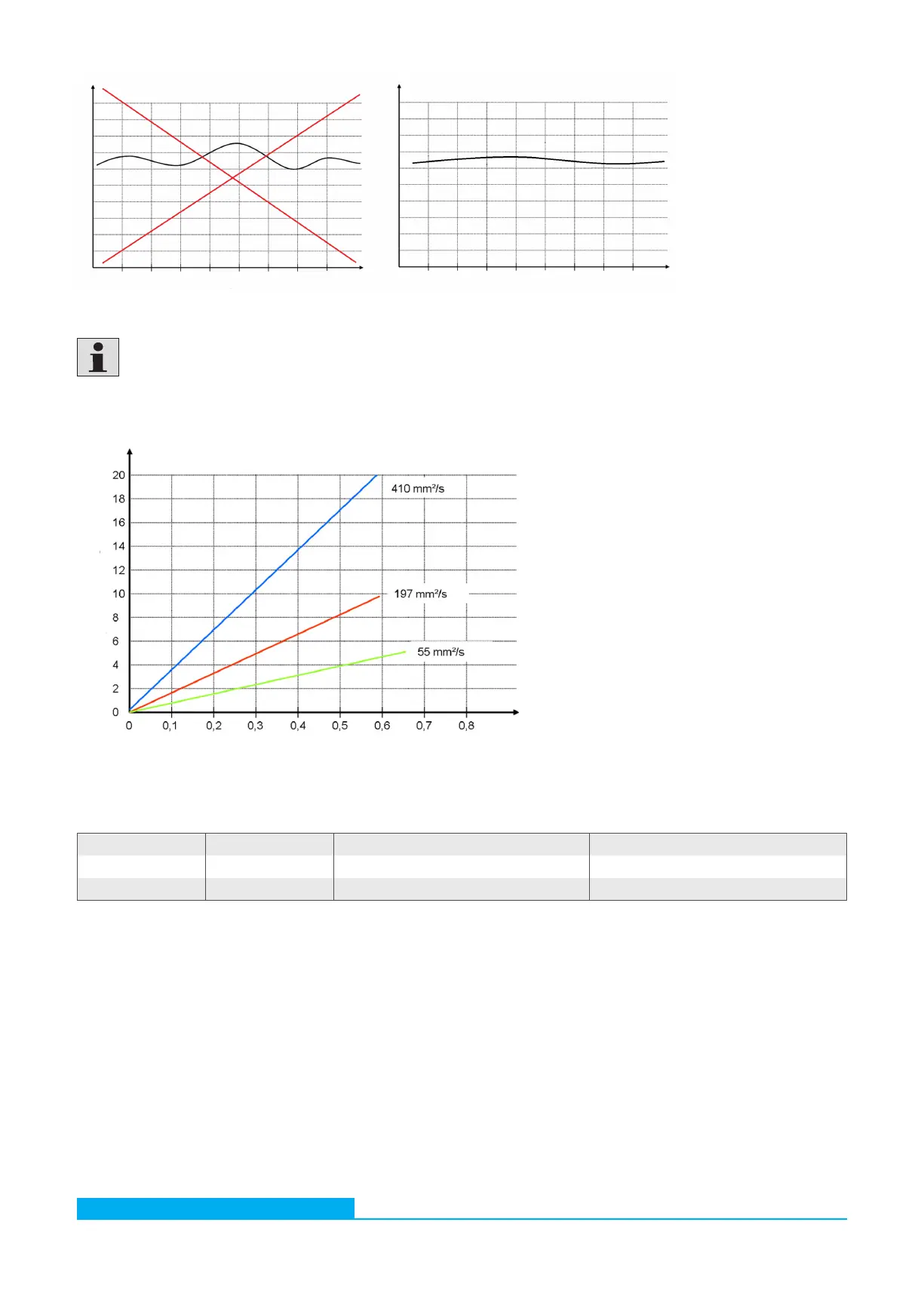
In the following figure the pressure difference depending on the volume flow is displayed for several viscosities. With a given volume
flow, the required pressure can be estimated.
∆p in bar
Flow rate in l/min
Fig. 8: ∆p-Q characteristics for varying viscosities without Minimess connections
Table 6: Mounting options
7.3 Mounting
The device has two options for mounting:
Orientation Mounting Tightening torque Screw depth
Bottom 4 x M5 Max. 4 Nm (strength class 8.8) Min. 5
+1
mm
Laterally 2 x M6 Max. 8 Nm (strength class 8.8) Min. 6
+1
mm