15
5.8 mains supply connection
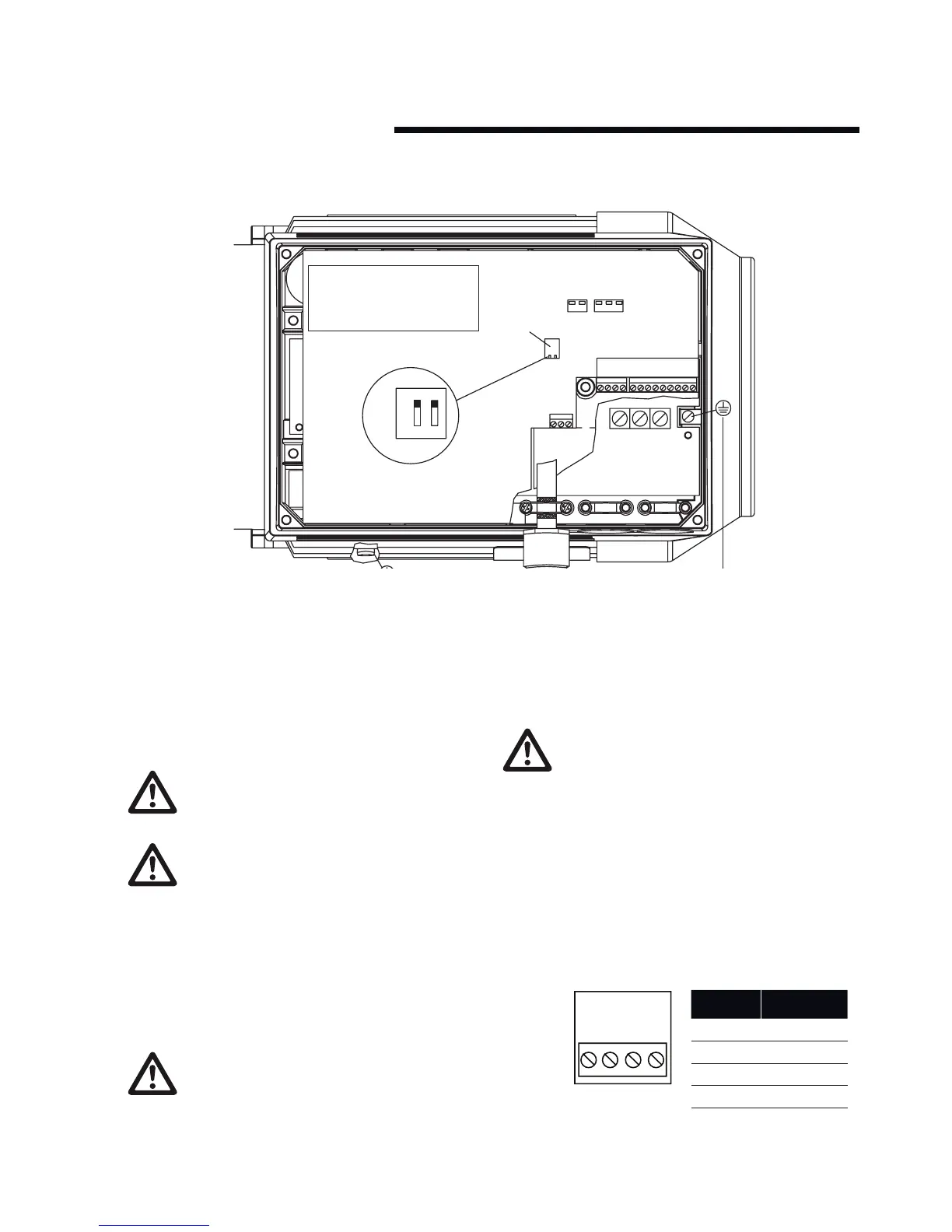
i Remove the inverter box cover, which is held by four screws
(6 on 5.5 and 7.5 kW units), to obtain access to the terminals.
ii Remove the detachable terminal plugs from the terminal
blocks x100 and x101 to obtain access to the mains terminals.
iii Lift only the corner of the black plastic cover by the cable
entries to expose the mains terminals l1, l2 and l3.
DO NOT lift or remove the entire plastic cover. This is
part of the inverters protective arrangements.
Mains Terminals L1, L2 and L3
Make sure that your mains supply corresponds to the
voltage required by the Design Envelope unit (see mo-
tor nameplate), tt and tn mains.
iv Remove the gland plug furthest from the drive end of the
motor (to the right in fig. 2) and feed the mains cable through
the hole.
v Connect the three mains phases to terminals l1, l2 and l3 and
the earth to the separate terminal provided.
DO NOT over-tighten the mains terminals as this will
damage the unit!
0.55 - 4.0 kW torque - 0.5 to 0.6 Nm
5.50 - 7.5 kW torque - 1.2 to 1.5 Nm
Earth terminal - 3.4Nm
vi Remove the middle gland plug and feed the control cable
through the hole (see the section on control connections for
wiring details).
vii The third entry is fitted with a plug kit to facilitate keypad
connection. Do not remove the kit or wiring unless as serial
communications link (to bms) is required.
You cannot change the rotational direction of the
pump by shifting around the input mains phases. The
direction of rotation is factory set.
5.9 control connections
Terminal blocks x100, x101 and x102 are used for control
connections. Individual terminal allocation is as follows:
x100 Terminals
The x100 terminals are used for data communications, either as
part of a serial communications network or for connection to the
cable gland mounted plug kit for key pad connection (Default).