18
6.1 lcp functions and operation
The functions of the control panel can be divided into
three groups:
•
Display
•Keysforchangingprogramparameters
•Keysforlocaloperation
All data is indicated by means of a 4 -line alphanumeric display,
which in normal operation is able show 4 measurements and 3
operating conditions continuously. During programming, all the
information required for quick, eective parameter Setup of the
Design Envelope Pump will be displayed. As a supplement to the
display, there are three leds for voltage, warning and alarm.
All program parameters of the Design Envelope Pump can be
changed immediately from the control panel, unless this
function has been blocked via parameter 018.
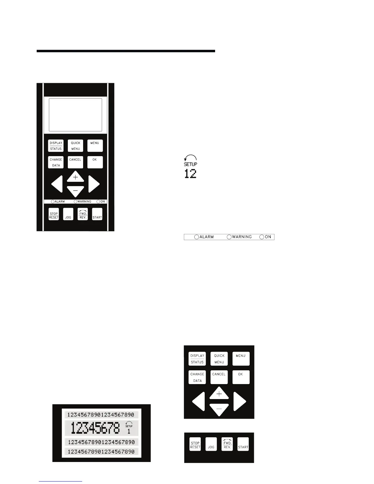
6.1.1 display
The lcd-display has rear lighting and a total of 4 alpha -
numeric lines together with a box that shows the direction of
rotation (arrow) and the chosen Setup as well as the Setup in
which programming is taking place if that is the case.
1st line shows up to 3 measurements continuously in normal
operating status or a text which explains the 2nd line.
2nd line shows a measurement with related unit continuously,
regardless of status (except in the case of alarm/warning).
3rd line is normally blank and is used in the menu mode to show
the selected parameter number or parameter group number
and name.
4th line is used in operating status for showing a status text or
in data change mode for showing the value of the selected
parameter.
An arrow indicates the direction of rotation of the pump
(factory set). Furthermore, the Setup which has been
selected as the Active Setup in parameter 004 is shown.
When programming another Setup than the Active
Setup, the number of the Setup which is being programmed will
appear to the right. This second Setup number will flash.
6.1.2 led's
At the bottom of the control panel is a red alarm led and a
yellow warning led, as well as a green voltage led.
If certain threshold values are exceeded, the alarm and/or
warning lamp lights up together with a status and alarm text on
the control panel. The voltage led is activated when the Design
Envelope Pump receives voltage; at the same time the rear
lighting of the display will be on.
6.1.3 control keys
The control keys are divided into functions. This means that
the keys between display and indicator leds are used for
parameter Setup, including choice of display indication during
normal operation.
Keysforlocalcontrolarefoundundertheindicatorleds.
1
st
line