Page 11 of 26
4.7 RELAY CONNECTIONS
The relays on the IVS are congured as follows:
Relay 1 - RUNNING
Terminal 01: Common
Terminal 02: Normal Open 240V AC
Terminal 03: Normal Closed 240V AC
Relay 2 - ALARM
Terminal 04: Common
Terminal 05: Normal Open 400V AC
Terminal 06: Normal Closed 240V AC
Figure 5. Relay Contact Details
Figure 4c. Mains and Grounding Connections for D1 and D2 units (380-480V - 150 to 350HP, 525-600V - 150 to 350HP)
95
11.7 relay connections
The relays on the Design Envelope are configured as follows:
relay 1 – running
•Terminal01: Common
•Terminal02: Normal open 240v ac
•Terminal 03: Normal closed 240v ac
relay 2 – alarm
•Terminal04: Common
•Terminal05: Normal open 400v ac
•Terminal06: Normal closed 240v ac
fig. 7 Relay contact details
04
05
06
01
02
03
240v ac, 2a
400v ac, 2a
240v ac, 2a
Relay 1
Relay 2
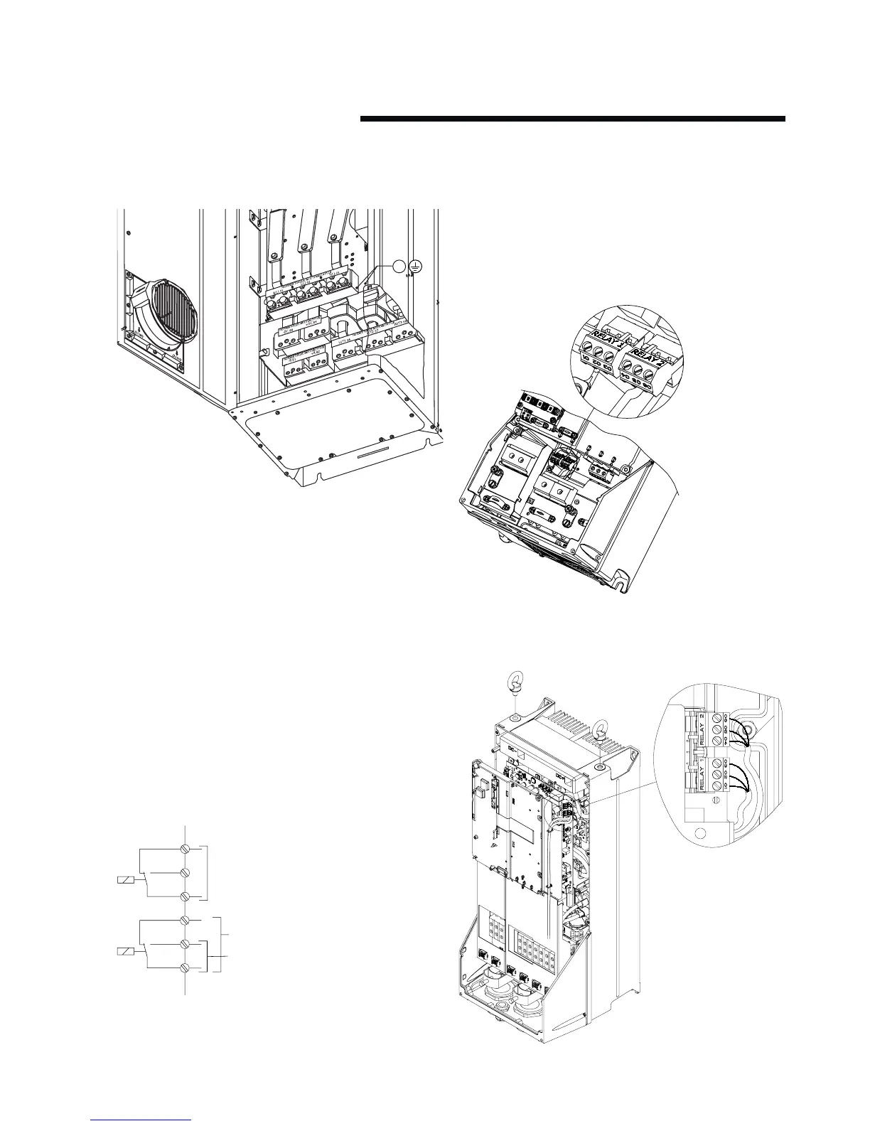
The following illustrations identify the location of the relays
within specific inverter sizes:
The illustrations in fig. 6, 7 and 8 identify the location of the
relays within specific inverter sizes:
fig. 8 Relay connection: terminals for a5, b1 and b2 units
fig. 9 Relay connection terminals for c1 and c2 units