41
12.0 programming, monitoring
and diagnostics
Design Envelope pumps incorporate an integrated graphical
local control panel (glcp).
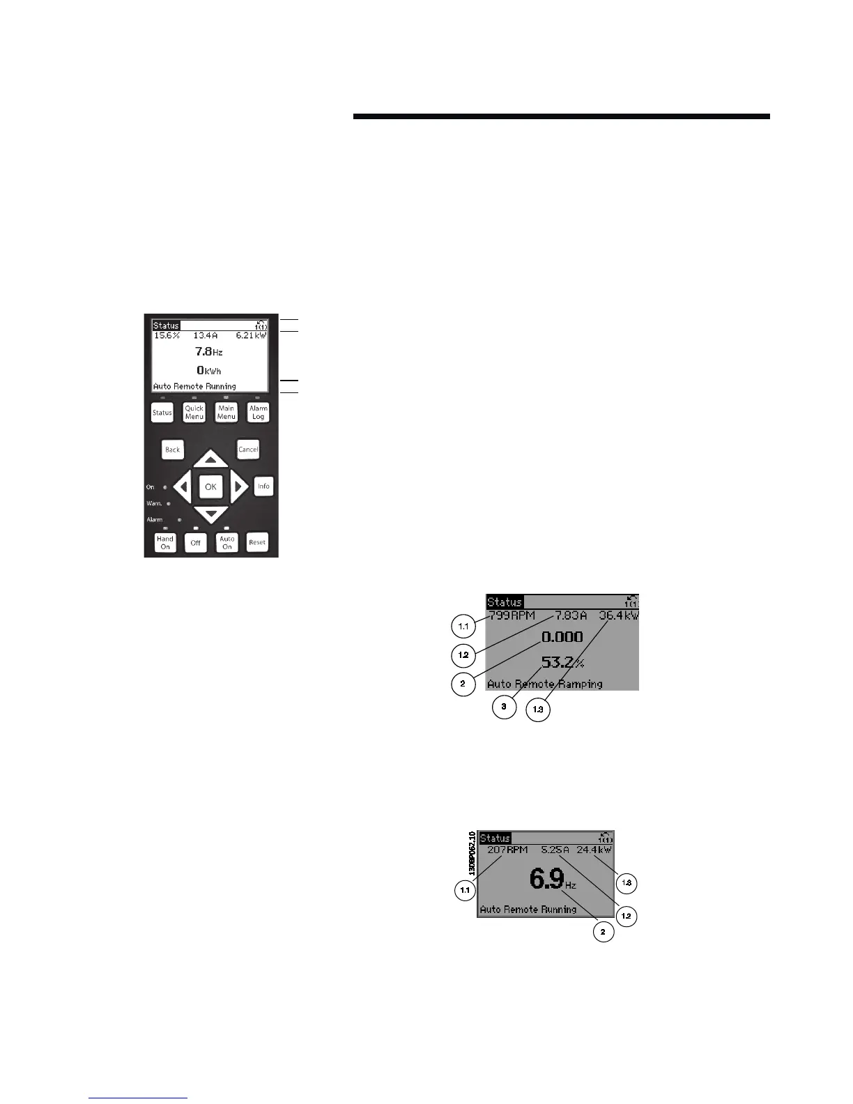
12.1 glcp functions and operation
The glcp is divided into four functional groups:
1
2
3
4
b
a
c
1 Graphical display with status lines.
2 Menu keys and indicator lights (leds) – selecting mode,
changing parameters and switching between
display functions.
3 Navigation keys and indicator lights (leds).
4 Operation keys and indicator lights (leds).
Graphical display:
The lcd-display is back-lit with a total of six alpha-numeric
lines. All data is displayed on the lcp which can show up to
five operating variables while in Status mode.
Display lines:
a Status line: Status messages displaying icons
and graphics.
b Line 1–2: Operator data lines displaying data and variables
de-fined or chosen by the user. By pressing the Status key,
up to one extra line can be added.
c Status line: Status messages displaying text.
The display is divided into three sections:
Top section (a) shows the status when in status mode or up
to two variables when not in status mode and in the case of
alarm/warning.
The number of the Active set-up (Sensorless mode being
setup 1) is shown.
The middle section (b) shows up to five variables with related
unit, regardless of status. In case of alarm/warning, the
warning is shown instead of the variables.
The Bottom section (c) always shows the state of the inverter
in Status mode.
It is possible to toggle between three status read-out displays
by pressing the Status key.
Operating variables with dierent formatting are shown in
each status screen — see below.
Status display I:
This read-out state is standard after start-up or initialisation.
Use Info to obtain information about the value/measurement
linked to the displayed operating variables (1.1, 1.2, 1.3, 2 and
3). See the operating variables shown in the display in this
illustration. 1.1,1.2 and 1.3 are shown in small size. 2 and 3 are
shown in medium size.
Status display II:
See the operating variables (1.1, 1.2, 1.3 and 2) shown in the
display in this illustration.
In the example, Speed, Motor current, Motor power and Fre-
quency are selected as variables in the first and second lines.
1.1, 1.2 and 1.3 are shown in small size. 2 is shown in large size.
Display Contrast Adjustment
Press Status and [p] for darker display
Press Status and [q] for brighter display