8
2.4 alignment
Design Envelope 4300 units are accurately aligned at the fac-
tory prior to being shipped and do not need re-aligning when
installed. Alignment on a Design Envelope 4300 unit may be
verified by assuring an equal and parallel gap between coupling
halves on both sides of the coupling.
operation
2.5 starting pump
Ensure that the pump turns freely by hand, or with
some gentle mechanical help such as a strap or Allen
key in coupling bolt.
Ensure that all protective guarding is securely fixed in position.
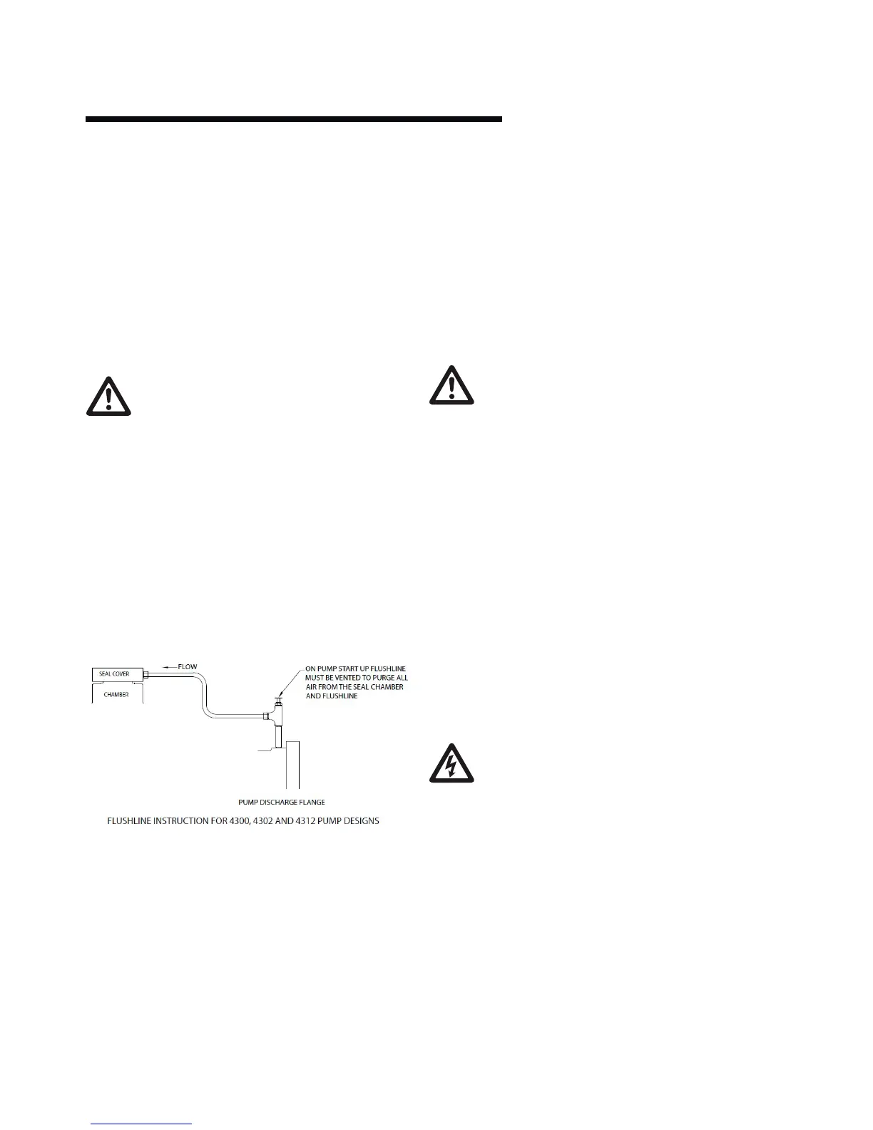
The pump must be fully primed on start up. Fill the pump
casing with liquid and rotate the shaft by hand to remove any
air trapped in the impeller. On Design Envelope 4300 any air
trapped in the casing as the system is filled must be removed by
the manual air vent in the seal flush line. Ensure entrained air is
removed from Design Envelope 4300 pumps, prior to starting,
through the air vent on the seal flush line. Open vent until clear
of air.
Design Envelope 4380 units are fitted with seal flush/vent lines
piped to the pump suction area. When these units operate,
residual air is drawn out of the pump towards the suction piping.
Bump or energize the motor momentarily and check that the
rotation corresponds with the directional arrow on the pump
casing (clockwise when viewed from drive end.).
Start the pump with the discharge valve closed and the suction
valve open, then gradually open the discharge valve when the
motor is at operating speed. The discharge valve may be
cracked or open slightly at start up to help eliminate trapped air.
When stopping the pump: Close the discharge valve and de-
energize the motor.
Do not run the pump against a closed discharge valve for an
extended period of time (a few minutes maximum.)
Should the pump be noisy or vibrate on start-up a common
reason is overstated system head. Check this by calculating the
pump operating head by deducting the suction pressure gauge
value from the discharge gauge reading. Convert the result into
the units of the pump head as stated on the pump nameplate
and compare the values. The system designer or operator
should be made aware of this soon as some adjustment may be
required to the drive settings to make the pump suitable for the
system as installed.
Check rotation arrow prior to operating the unit.
The rotation of all Armstrong Vertical In-Line units is
“clockwise” when viewed from the drive end.
(Looking from on top of/behind the motor).
2.6 general care
Vertical In-Line pumps are built to operate without periodic
maintenance, other than motor lubrication on larger units. A
systematic inspection made at regular intervals, will ensure
years of trouble-free operation, giving special attention to
the following:
• Keepunitclean
• Providethemotorwithcorrectlysizedoverloadprotection
Keepmoisture,refuse,dustorotherlooseparticlesawayfrom
the pump and ventilating openings of the motor.
• Avoidoperatingtheunitinoverheatedsurroundings
(Above 100°f/40°c).
warning:
Whenever any service work is to be performed on
a pumping unit, disconnect the power source to the
driver, lock it o and tag with the reason. Any
possibility of the unit starting while being serviced
must be eliminated.
If mechanical seal environmental accessories are
installed, ensure water is flowing through the sight
flow indicator and that filter cartridges are replaced
as recommended. (See Armstrong files 43.85 and
43.86 for seal environmental instructions).