45
fig. 11 quadratic control settings
p22-86
h (head)
q (flow)
p22-87
h
min
h
design
set point
control curve
a
n
de sign
n
ra ted
p22-89
p20-21
Design Envelope pumps can replicate this control without the
need for the remote sensor. As the flow required by the system
is reduced, the pump automatically reduces the head developed
according to the pre-set control curve.
It is often found that using a remote dierential pressure sensor
to sense the pressure across a remote load could theoretically
result in loads close to the pump being under-pumped. The
situation would be where the load at a loop extremity is satis-
fied and the control valve closes while a load close to the pump
needs full flow. The probability of this occurring is remote but
it is possible. One answer to this is to move the sensor closer
to the pump (two-thirds out in the system is a popular recom-
mendation) although physically re-positioning the sensor at
commissioning stage can be a costly exercise. With Sensorless
pump control it is possible to replicate the moving of a sensor by
increasing the head setting h
min
.
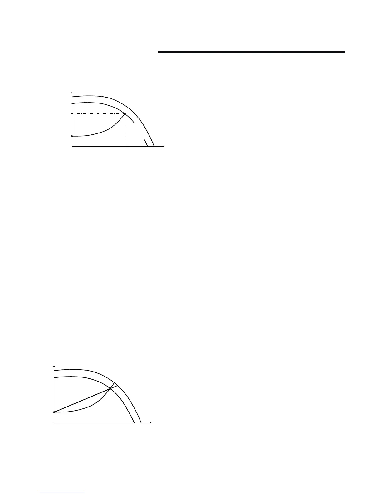
13.1.1 settings for quadratic (control curve)
pressure control
The design duty head and flow of the pump (provided at time of
order) is shown as point ’A’ in figure 11 in column 1.
fig. 12 curve approximation settings
h (head)
q (flow)
p22-81 0%
100%
control curve
In order for the controller to determine the true fit and position
of the control curve it is necessary to set some specific param-
eters with data relating to specific points within the operating
range of the pump. There are two ways of programming the
parameters depending on whether the speed at the design duty
is known or unknown.
Speed at Required System Design Point is known
(Refer to fig. 11):
1 Set the design head, h
design
, value in par. 20-21 (Setpoint 1),
after setting unit of head in par. 20–12 (Reference/
Feedback unit)
2 Set the speed of the pump at design head, h
design
, and design
flow using par. 22–86 (Speed at Design Point [Hz])
3 Set the minimum head required, h
min
, using par. 22–87
(Pressure at No-Flow Speed).
4 Adjust the shape of the control curve if required using par.
22–81 as shown in figure 12.
13.2 constant pressure control
Design Envelope pumps can be configured to maintain a con-
stant pump head in a system as the demand varies. This eec-
tively simulates the mounting of a dierential pressure sensor
at, or near, the pump.
13.2.1 settings for constant pressure control
1 To revert to this mode of control simply follow these steps:
Set the design head, h
design
, value in par. 20–21 (Setpoint 1).
In the units set in par.20–12 (Reference/feedback unit.)
2 Turn o flow compensation by setting par. 22-80 to
‘Disabled’ [0]
13.3 changing control modes
13.3.1 change to external sensor control
1 Change parameter 0-10 from 1 to 2
2 Connect the sensor to terminals 54 (+) and 55 (-)
3 Move switch s202 (beside terminal input 54) to on if the
speed command is 4-20mA, or leave it o if it’s 0-10Vdc
4 If the sensor signal is neither 0-10Vdc nor 4-20mA, enter the
correct voltage or input range in parameters 6-10 to 6-13
5 Enter the sensor and setpoint data in the parameters
listed below