6
4300
4380
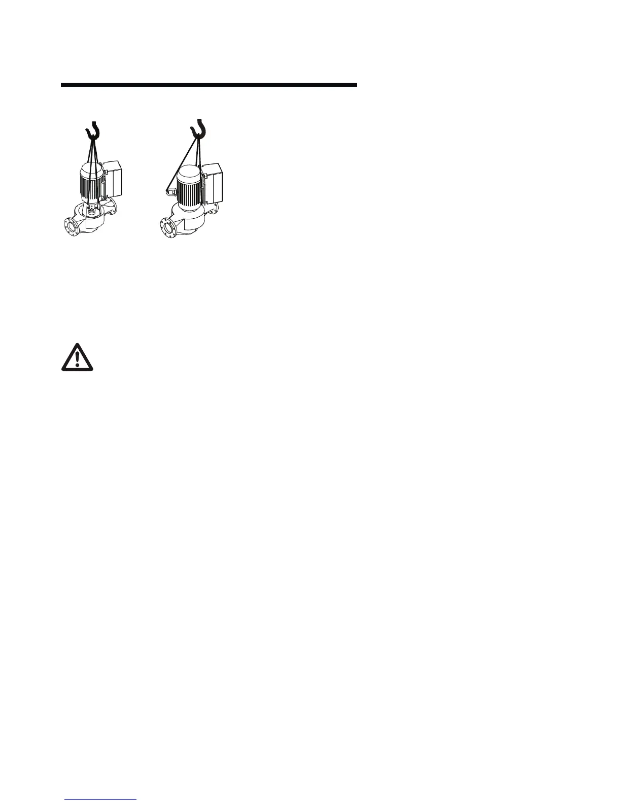
Remove coupling guard
and place lifting straps on
each side of coupling, use
spacer bar if necessary to
protect the integrated con-
trols and motor fan cover.
Remove the motor eye-bolt
and install a swivel hoist
ring tied to a lifting strap.
Place secondary lifting
straps securely around mo-
tor feet (and/or spacers).
important:
Do not run the pump for any length of time under very
low flow conditions or with the discharge valve closed.
To do so could cause the water in the casing to reach
super heated steam conditions and will cause premature failure
and could cause serious and dramatic damage to the pump and
surrounding area.
2.0 installation
2.1 location
In open systems, locate the unit as close as practical to the
liquid being pumped, with a short, direct suction pipe. Ensure
adequate space is left above and around the unit for operation,
maintenance, service and inspection of parts.
In closed systems, where possible, the pumps should be in-
stalled immediately downstream of the expansion tank /make-
up connection. This is the point of zero pressure change and is
necessary for eective pump operation. Do not install more than
one expansion tank connection into any closed hydronic system.
Electric motor driven pumps should not be located in damp or
dusty location without special protection.
Airflow into the motor and/or motor fan should not
be obstructed.
2.2 installation
When installing vertical in-line pumps, an important consider-
ation to accrue full added-value from the pump design is to en-
sure that the pump is pipe-mounted and free to ‘float’ with any
movement, expansion and contraction of the piping. Should any
vertical in-line pump use supports to the structure it is impera-
tive that no pipe strain is imposed on the pump flanges. Tell-tale
pieces of equipment such as springs or ‘wae’ style neoprene
isolation pads that distort with pressure to indicate added piping
weight, should be used under pump supports should the pump
not be truly pipe mounted.
Design Envelope 4300 and 4380 cannot be mounted with shafts
in the horizontal position.
Various installation arrangements are detailed on Pages 9–12
All Design Envelope 4300 pumps contain a tapped hole in the
motor bracket above the discharge flange to drain condensate
buildup of seal leakage. (fig. 2.14)
2.2.1
Vertical In-Line pumps may be installed directly in the system
piping with no additional support. Pipe hangers are simply sized
for the additional weight of the pumping unit. Many pumps are
installed in this manner and can be mounted at sucient height
to take zero floor space. (fig. 2.1)
2.2.2
Piping in many mechanical rooms is hung close to the ceiling
and larger pumps are mounted near ground level for ease of
maintenance. fig. 2.2 illustrates such an arrangement with the
piping supported at the ceiling and the vil unit installed with an
Armstrong Suction Guide and Flo-Trex valve. Many very large
vil pumps are installed in this manner.
2.2.3
Should additional space saving be required the discharge spool
piece may be replaced by a long-radius elbow.
2.2.4
fig 2.4 illustrates a similar arrangement to fig 2.2 with
additional floor mounted pipe-stools isolated from the structure
by ‘wae’ style neoprene isolation pads under the Armstrong
Suction Guide and Flo-Trex valve.
2.2.5
Floor mounted saddle supports (fig. 2.5) are typical for condens-
er water pumps where cooling tower base is at the mechanical
room elevation.
2.2.6
Where required, additional floor support may be used as shown
in Fig. 2.6. Note that the pump should not be rigidly attached to
the column. Leave a small gap between pump and column or
install a ‘wae’ isolation pad under the pump. It is critical that
piping be installed in such a manner that the pump does not
become a pipe support.