13
3.0 ce conformities
For Declaration of Conformity certificates please
contact Armstrong.
The Design Envelope product conforms to the requirements
in the following directive(s), standard(s) or other normative
document(s):
low voltage directive 2006/95/ec
emc directive 2004/108/ec
machinery directive 2006/42/ec
ecodesign directive 2009/125/ec
4.0 mechanical installation
Install the Design Envelope unit with adequate access for routine
maintenance. Adequate space, particularly at the fan inlet (50
mm), is necessary to facilitate airflow. Where several Design En-
velope units are installed in close proximity, care must be taken
to ensure that there is no re-circulation of exhausted warm air.
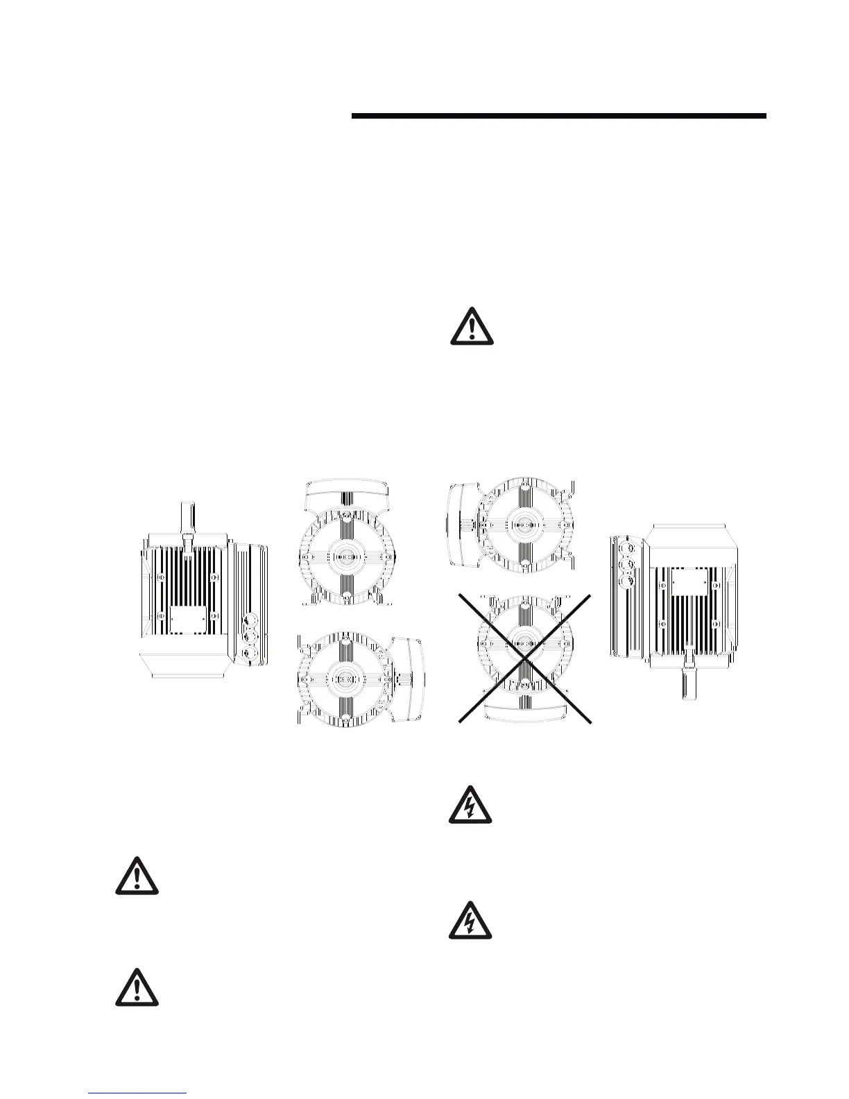
With reference to fig. 3, the pump should not be
installed with the inverter in the underside position.
This guidance pertains to all pump types and
overrides any instruction in the particular pump
Installation, Operation and Maintenance Instruction.
integrated controls
Power Rating 0.55 kW - 7.5 kW
4.1 enclosure rating
The standard enclosure rating for Design Envelope
pumps is ip55. If the pump is to be installed in a wet or
dusty environment then a higher enclosure rating may
be required (ip56 or ip66 option).
4.2 ambient temperature
To avoid the inverter unit getting overheated, the
ambient temperature is not to exceed 40°c and the 24
hour average temperature is not to exceed 35°c. If the
ambient temperature is in the range of 40°c - 55°c, a
reduction of the service life of the inverter part is to be expected.
5.0 electrical installation
All electrical connections should be carried out by a
qualified and authorised electrician in accordance with
local site regulations and the latest issue of the
iee regulations.
safety, risk of death
Before removing the inverter cover, the system must
be disconnected from the mains supply. After switch-
ing o wait for at least five minutes for the capacitors
to discharge before opening the cover.
fig. 3 Allowable Installation Orientation - On-board Inverter Position