17
iii Constant curve mode - bms speed control
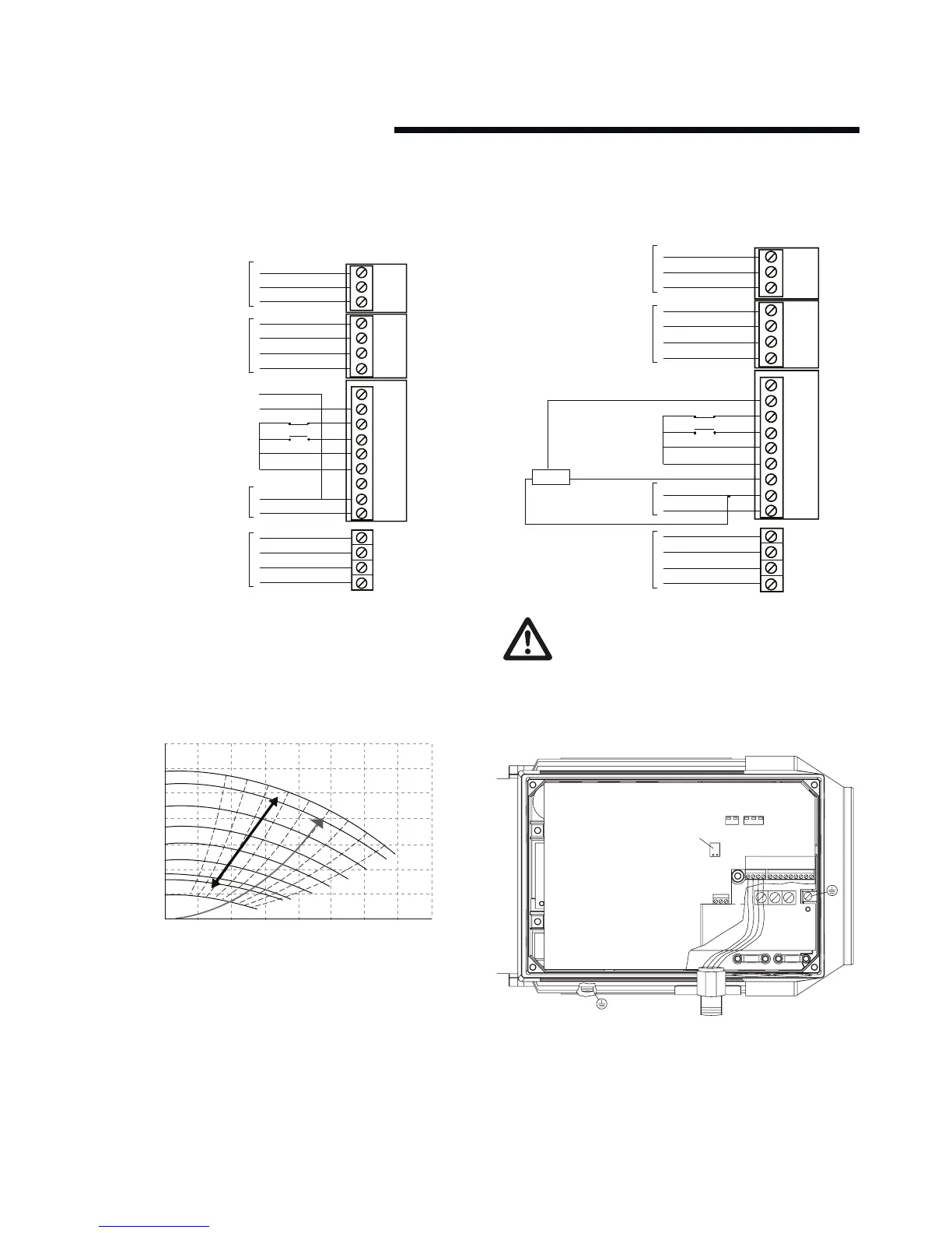
Where the Building Management System is to be used for
speed control it is necessary to disable sensorless control
and provide the unit with a 0 - 10v dc speed reference signal.
As shown above, in Constant curve mode the pump will speed
up and slow down according to the voltage level of the reference
signal. On a unit configured for 50 hz pump speed the reference
signal is scaled (by default) so that 0v on x100 terminal 2 will
equate to 0 hz and 10v will equate to 50 hz.
iv Constant curve mode - Potentiometer speed control
If a potentiometer is to be installed for manual control of
pump speed then the control connections will be as follows:
The recommended minimum speed for Design
Envelope pumps is 580 rpm. Running for long periods
below this speed can damage the mechanical seal.
6.0 programming, monitoring
and diagnostics
A key pad tool (lcp) is available for Design Envelope Pumps as
an option. The lcp gives the user full programming and monitor-
ing capabilities and it is recommended that at least one lcp and
cable kit are purchased for each installation site.
The lcp is connected via a cable to the ‘plug kit’ mounted in one
of the inverter cable entries as shown above.
1
2
3
x102
1
2
3
4
x100
1
2
3
4
L1
L2
L3
PE
5
6
7
8
9
x101