installation &
operating instructions
Design Envelope 4300 and 4380 vertical in-line
pumping unit with integrated controls
38
11.8.1 access to terminals
Page 14 of 26
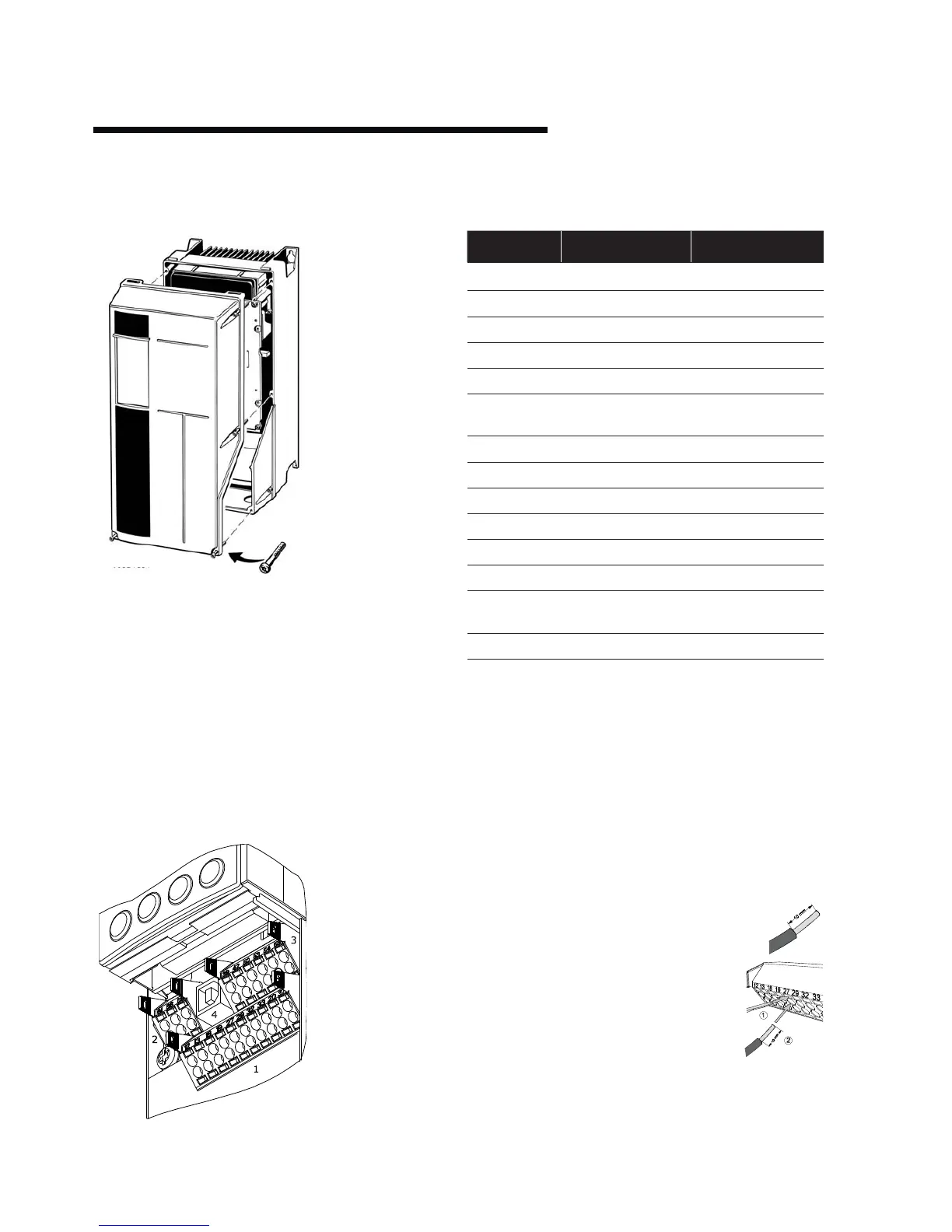
4.8.1 ACCESS TO TERMINALS
Remove front-cover to access control terminals. For D1 and
D2 chassis IVS units access swings open. (see Fig. 2.13) .
When replacing the front cover, please ensure proper fasten-
ing by applying a torque of 2 Nm.
4.8.2 CONTROL TERMINALS
With reference to gure 10:
1. 10 way plug for digital I/O
2. 3 way plug for RS485 Bus
3. 6 way plug for analogue I/O
4. USB Connection
Control terminal functions and factory settings are as follows:
*Note that Analogue inputs AI53 and AI54 can be either Volt-
age (0-10V) or Current (4-20mA) input and by default both
inputs are set to Voltage.
Switches S20
1 and S202 (see gure 9) are used to congure
the analogue inputs as follows:
S201 (AI53) OFF = Voltage, ON = Current
S202 (AI54) OFF = Voltage, ON = Current
Inserting Cables into Control Terminals
i) Strip 10mm of insulation from the cable:
ii) Insert a suitable terminal screwdriver as
shown and then push the cable into the terminal.
Iii) Remove the terminal screwdriver and
check the terminal has gripped the cable
by gently pulling it.
Note: Terminal plugs can be easily re-
moved for improved access when making
connections.
Terminal No. Type / Description Factory Setting
1,2,3 Relay 1 Running
4,5,6 Relay 2 Alarm
12 Supply +24V DC
13 Supply +24V DC
18 Digital Input Start
19 Digital Input Pump Operating Mode
20 Common 0V
27 Digital Input Low Water Inter
lock
29 Digital Input No Operation
32 Digital Input No Operation
33 Digital Input No Operation
37 Digital Input No Operation
42 Analogue Output Output Frequency
(4-20mA - 0-100Hz)
53 Analogue Input Reference (0-10V)*
54 Analogue Input Feedback (0-10V)*
Figure 10. Control Connections
Remove front-cover to access control terminals. For d1 and
d2chassis ivs 102 units accessswings open. (see Fig. 2.13).
When replacing the front cover, please ensure proper fastening
by applying a torque of 2 Nm.
11.8.2 control terminals
With reference to figure 10:
fig. 10 control connections
Control terminal functions and factory settings are
as follows:
terminal no. type / description factory setting
1,2,3 Relay 1 Running
4,5,6 Relay 2 Alarm
12 Supply +24v dc
13 Supply +24v dc
18 Digital input Start
19 Digital input Pump operating
mode
20 Common ok
27 Digital input Low water interlock
29 Digital input No operation
32 Digital Input No operation
33 Digital input No operation
37 Digital input No operation
42 Analogue output Output frequency
(4-20mA - 0-100Hz)
53 Analogue input Reference (0-10v)*
54 Analogue input Feedback (0-10v)*
*Note that Analogue inputs ai53 and ai54 can be either Voltage
(0-10v) or Current (4-20ma) input and by default both inputs
are set to Voltage. Switches s201 and s202 (see figure 9) are
used to configure the analogue inputs as follows:
s201 (ai53) o = Voltage, on = Current
s202 (ai54) o = Voltage, on = Current
Inserting Cables into Control Terminals
i Strip 10mm of insulation from the cable:
ii Insert a suitable terminal screwdriver
as shown and then push the cable into
the terminal.
iii Remove the terminal screwdriver and
check the terminal has gripped the cable
by gently pulling it.
Note: Terminal plugs can be easily removed
for improved access when making connections.
Page 14 of 26
4.8.1 ACCESS TO TERMINALS
Remove front-cover to access control terminals. For D1 and
D2 chassis IVS units access swings open. (see Fig. 2.13) .
When replacing the front cover, please ensure proper fasten-
ing by applying a torque of 2 Nm.
4.8.2 CONTROL TERMINALS
With reference to gure 10:
1. 10 way plug for digital I/O
2. 3 way plug for RS485 Bus
3. 6 way plug for analogue I/O
4. USB Connection
Control terminal functions and factory settings are as follows:
*Note that Analogue inputs AI53 and AI54 can be either Volt-
age (0-10V) or Current (4-20mA) input and by default both
inputs are set to Voltage.
Switches S20
1 and S202 (see gure 9) are used to congure
the analogue inputs as follows:
S201 (AI53) OFF = Voltage, ON = Current
S202 (AI54) OFF = Voltage, ON = Current
Inserting Cables into Control Terminals
i) Strip 10mm of insulation from the cable:
ii) Insert a suitable terminal screwdriver as
shown and then push the cable into the terminal.
Iii) Remove the terminal screwdriver and
check the terminal has gripped the cable
by gently pulling it.
Note: Terminal plugs can be easily re-
moved for improved access when making
connections.
Terminal No. Type / Description Factory Setting
1,2,3 Relay 1 Running
4,5,6 Relay 2 Alarm
12 Supply +24V DC
13 Supply +24V DC
18 Digital Input Start
19 Digital Input Pump Operating Mode
20 Common 0V
27 Digital Input Low Water Inter
lock
29 Digital Input No Operation
32 Digital Input No Operation
33 Digital Input No Operation
37 Digital Input No Operation
42 Analogue Output Output Frequency
(4-20mA - 0-100Hz)
53 Analogue Input Reference (0-10V)*
54 Analogue Input Feedback (0-10V)*
Figure 10. Control Connections
1 10-way plug for
digital i/0
2 3-way plug for
rs485 bus
3 6-way plug for
analogue i/0
4 usb connection