39
11.8.3 connection examples
Design Envelope pumps can be configured in four main ways:
i Sensorless
ii Closed loop – with feedback sensor
iii Constant curve mode – Potentiometer Control
iv Constant curve mode – bms signal
iv.i Full speed override
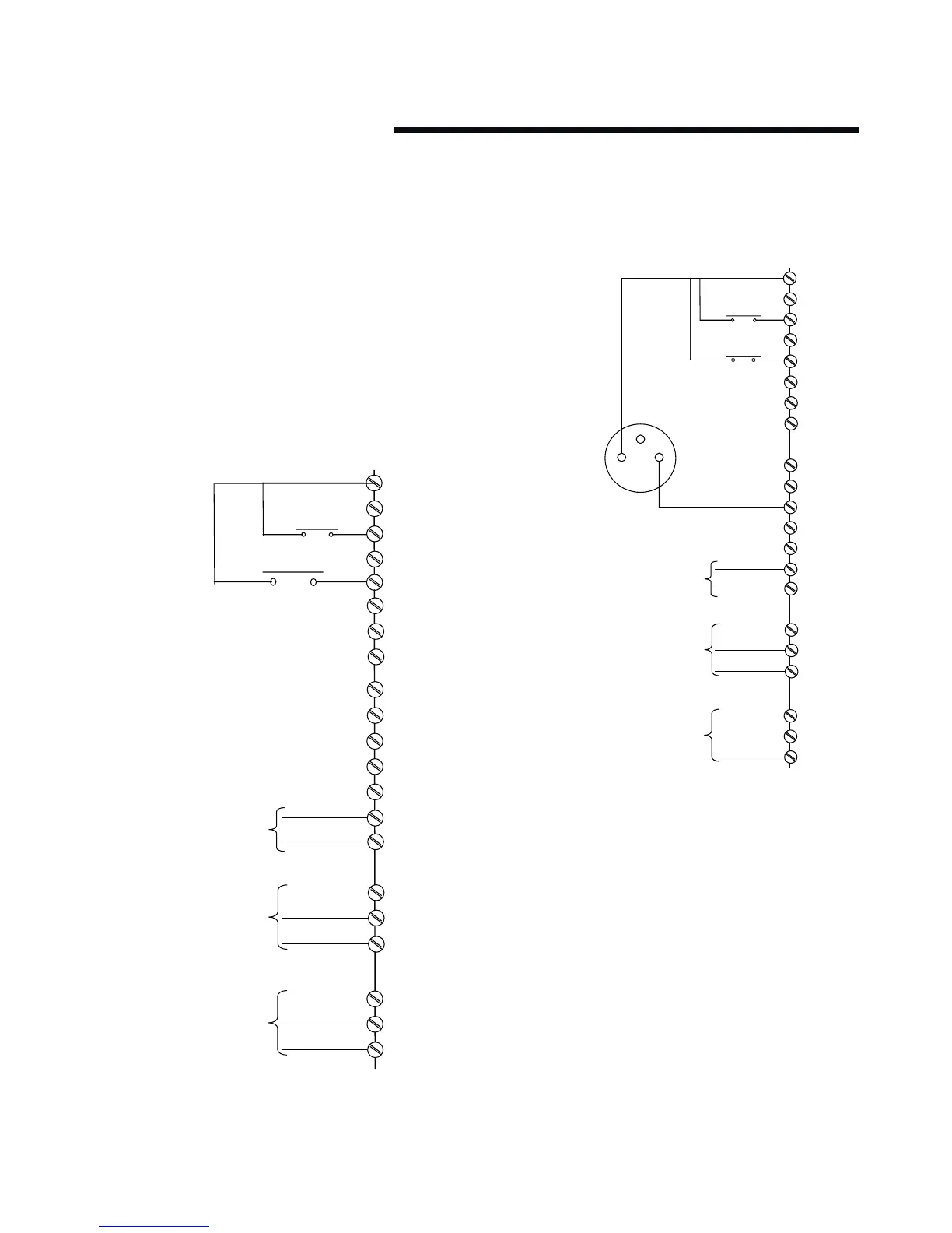
i sensorless
Design Envelope pumps are factory configured to be
connected as shown below.
ii closed loop – with sensor feedback
To control the pump based on a 4-20mA feedback signal
from a sensor use the following connection.
12 (+24v )
20 (0v )
18 (d in)
Start Signal
Output Frequency
4-20mA Analog ue Out
Running Output
Alarm Output
19 (
(
d
d
in
in
)
)
50 (10v)
53 (Ain)
54 (Ain)
55 (0v )
42 (Aout)
39 (Aout)
2 (r1 n/o)
3 (r1 n/c)
1 (r1 com)
5 (R2 N/O)
6 (R2 N/C)
4 (R2 COM)
29 (d in)
32 (d in)
33 (d in)
27
24v
12 (+24v )
20 (0v )
18 (d in)
Start Signal
Output Frequency
4-20mA Analogue Out
Running Output
Alarm Output
19 (d in)
27 (d in)
29 (d in)
32 (d in)
33 (d in)
50 (10v)
53 (Ain)
54 (Ain)
55 (0v )
42 (Aout)
39 (Aout)
2 (r1 n/o)
3 (r1 n/c)
1 (r1 com)
5 (R2 N/O)
6 (R2 N/C)
4 (R2 COM)
Pressure Sensor
(0-10 bar / 4 -20ma)
Feedback from Sensor
4-20mA - Input t54
Power Supply (24 vdc)
for sensor t13=24v