40
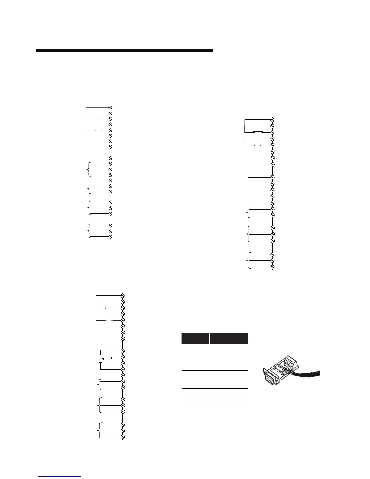
iii constant curve mode – bms signal
When the Building Management System is to be used for
speed control it is necessary to disable sensorless control
and provide the unit with a 0-10vdc speed reference signal.
iv constant curve mode – potentiometer
To control the pump based on a 0-10v potentiometer signal
use the connections below.
iv.i full speed over ride
It may be required to run the pump at full speed without
automatic speed control (eg during system commissioning).
This can be achieved without programming changes by
making the connections below.
11.8.4 remote lcp keypad wiring
For large Design Envelope units with remote lcp keypad, see
wiring arrangement below.
lcp wiring arrangement
terminal wire color
1 Green
2 Brown
3 Red
4 Yellow
5 Black
6 Orange
7 Blue
8 Purple
9 Grey
2 (r1 n/o)
3 (r1 n/c)
1 (r1 com)
5 (r2 n/o)
6 (r2 n/c)
4 (r2 com)
0-10v Signal from
bms
Input
t53 (common t55)
Output Frequency
4-20mA Analogue Out
12 (+24v )
20 (0v )
18 (d in)
Start Signal
Running Output
Alarm Output
19 (d in)
27 (d in)
29 (d in)
32 (d in)
33 (d in)
50 (10v)
53 (Ain)
54 (Ain)
55 (0v )
42 (Aout)
39 (Aout)
Low Water Signal
12 (+24v )
20 (0v )
18 (d in)
Start Signal
Running Output
Alarm Output
19 (d in))
27 (d in))
29 (d in))
32 (d in))
33 (d in))
50 (10v)
53 (Ain)
54 (Ain)
55 (0v )
42 (Aout)
39 (Aout)
2 (r1 n/o)
3 (r1 n/c)
1 (r1 com)
5 (r2 n/o)
6 (r2 n/c)
4 (r2 com)
0-10v Derived from
1k
Potentiometer into Input
t53 (common t55)
Output Frequency
4-20mA Analogue Out
Low Water Signal
2 (r1 n/o)
3 (r1 n/c)
1 (r1 com)
5 (r2 n/o)
6 (r2 n/c)
4 (r2 com)
Output Frequency
4-20mA Analogue Out
12 (+24v )
20 (0v )
18 (d in)
Start Signal
Running Output
Alarm Output
19 (d in)
27 (d in)
29 (d in)
32 (d in)
33 (d in)
50 (10v)
53 (Ain)
54 (Ain)
55 (0 v)
42 (Aout)
39 (Aout)
Link
10vdc (t50 ) into
Analogue Input t53
Low Water Signal