23
7.0 sensorless operation
Sensorless control is an innovative concept in glanded circulat-
ing pumps. Pump performance and characteristic curves for ten
dierent speeds are embedded in the memory of the speed con-
troller during manufacture. This data includes power, pressure
and flow across the flow range of the pump. During operation,
the power and speed of the pump are monitored, enabling the
controller to establish the hydraulic performance and position in
the pumps head-flow characteristic.
These measurements enable the pump to continuously identify
the head and flow at any point in time, giving accurate pressure
control without the need for external feedback signals. Patented
software technology within the controller ensures trouble-free
operation in all conditions. Incorporating the pumps hydraulic
data into the controller and removing sensors results in true
integration of all components and removes the risk of
sensor failure.
7.1 default operating mode - quadratic
pressure control
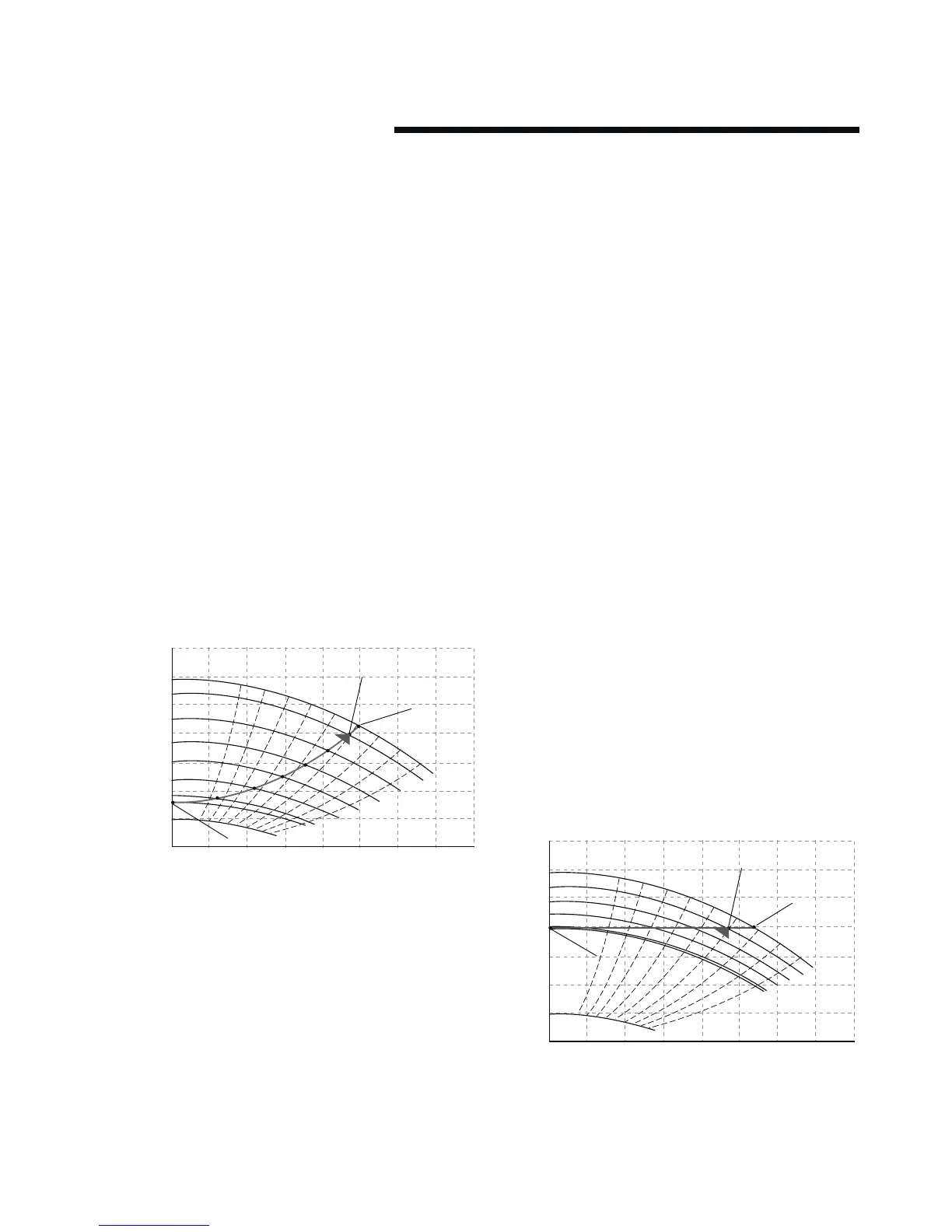
The default control mode for Design Envelope pumps ‘Quadratic
Pressure Control’ where the controller is set to control the speed
according to a ‘control curve’ between max and min flow
(see above diagram). It is widely recognised that fitting a
dierential pressure sensor at the most remote load, across the
supply piping and return piping encompassing the valve & coil
set, is the best installation scheme for energy eciency.
Design Envelope pumps can replicate this control without the
need for the remote sensor. As the flow required by the system
is reduced, the pump automatically reduces the head developed
according to the pre-set control curve. It is often found that us-
ing a remote dierential pressure sensor to sense the pressure
across a remote load could theoretically result in loads close to
the pump being underpumped.
The situation would be where the load at a loop extremity is
satisfied and the control valve closes while a load close to the
pump needs full flow.
The probability of this occurring is remote but it is possible. One
answer to this is to move the sensor closer to the pump (two-
thirds out in the system is a popular recommendation) although
physically re-positioning the sensor at commissioning stage can
be a costly exercise. With Sensorless pump control it is possible
to replicate the moving of a sensor by adjusting the head setting
‘Head Q
min
’.
7.1.1 description of settings
The design duty head and flow of the pump (provided at time of
order) is defined by the controller as ’head working point’ and
’flow working point’. The minimum head (Head Q
min
) is defined
as a percentage of the head working point. The maximum
controllable head (Head Q
max
) is the head developed when the
pump reaches full speed and is calculated by the other two
head settings.
7.1.2 setting parameters for quadratic
pressure control
• Parameter 716 - Enter the head (kPa) at design flow.
•
Parameter 717
- Enter the design flow (l/s).
•
Parameter 707
- Enter the minimum head requirement
(as a percentage of p716).
• Parameter 705 - Quadratic Head should be set to ’on’.
•
Parameter 798
- This is a calculated value from the
settings above and should not be changed.
7.2 constant pressure control
Design Envelope pumps can be configured to maintain a con-
stant pressure in a system as the demand varies. This eectively
simulates the mounting of a dierential pressure sensor at, or
near, the pump.
0
0
20
40
60
80
100
120
10
51
1450 rpm
1388 rpm
1270 rpm
1150 rpm
1040 rpm
920 rpm
801 rpm
750 rpm
580 rpm
62
71
77
81
82
81
77
1
2
3
4
5
6
7
71
20 30 40 50 60 70 80
flow – L/s
water, spgr= 1.0000