16
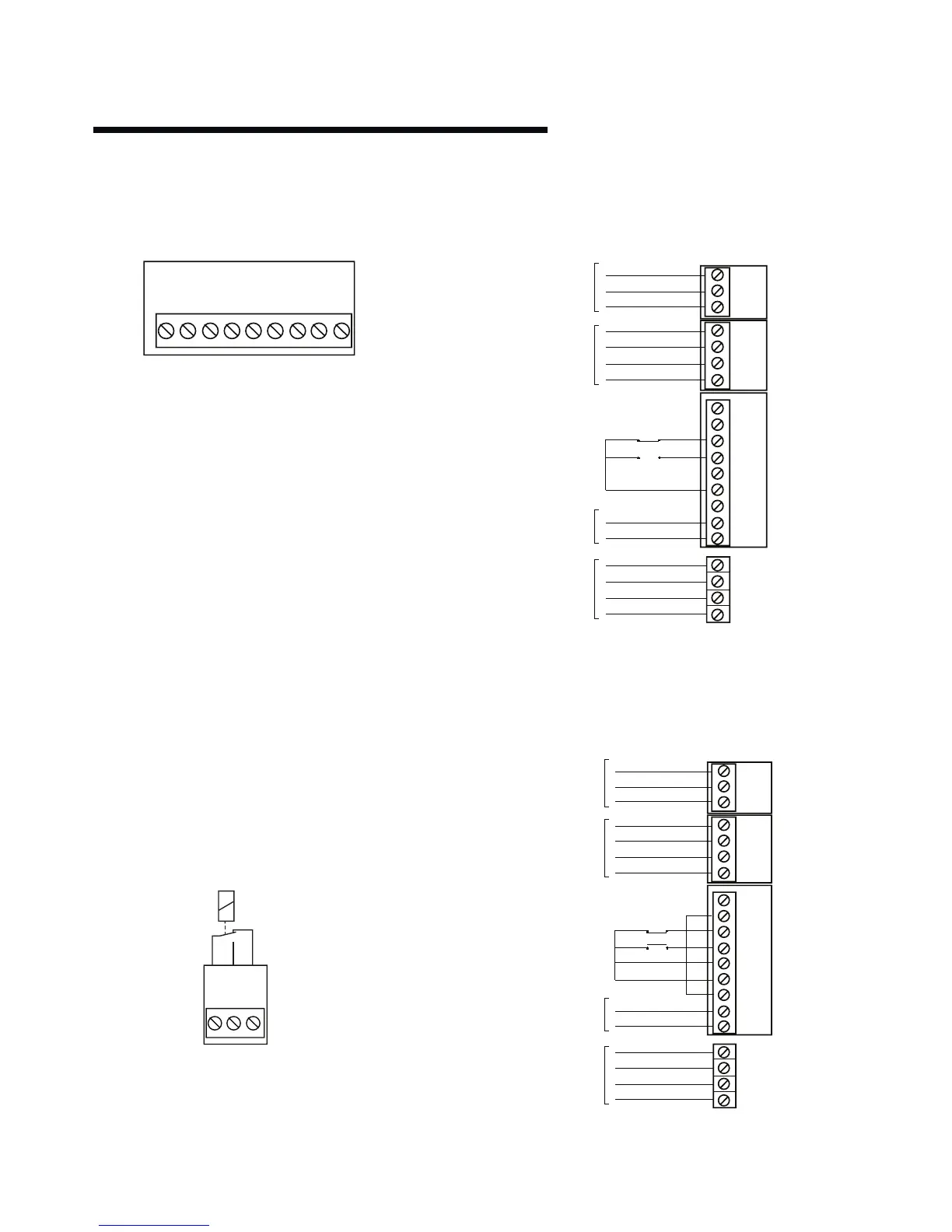
x101 Terminals - Control Terminals
The x101 terminals are used for analogue and digital signals that
will determine the operation of the pump(see the section on
Control Modes).
• Terminal 1 - 4-20 mA input for a remote feedback device
(when Sensorless control is not used).
•
Terminal 2
- 0-10v input for a reference signal (when
Sensorless control is not used).
•
Terminal 3
- Digital input for a low water device (pump only
runs if input is ‘logic 1’) - factory linked with zero ohm resistor
to terminal 6.
• Terminal 4 - Digital input for pump start (pump enabled when
‘logic 1’).
•
Terminal 5
- Digital input for pump mode (if left at ‘logic 0’
then pump will be in sensorless mode).
•
Terminal 6
- 24v dc supply for terminals 3 to 5 (max 150 mA).
• Terminal 7 - 10v dc supply for terminal 2 when used with a
potentiometer (max 15 mA).
•
Terminal 8
- 0v for terminals 1 to 7 and 9.
•
Terminal 9
- Digital output for ‘pump fault’ connection to bms
(voltage level will be 24v dc when pump has a fault).
attention:
Terminal 9 is not a volt-free contact. Connection of an external
voltage will destroy the unit.
x102 Terminals - Pump Running
The x102 terminals provide a relay changeover contact for
identification of pump running.
Terminals 1
- 2 will be made when the pump is running.
Voltage level at contact/load (ac) 250v ac, 5a Voltage level
at contact/load (dc) 30v dc, 5a; 40v dc, 2a; 100v dc, 0.5a
5.9.1 connection examples
There are many ways that an Design Envelope pump can be
configured. The following is some examples of the most
common control configurations.
i Sensorless Pressure Control - Connection Details
Design Envelope pumps are factory configured to be
connected as shown below. For a description of sensorless
pressure control please refer to the programming section.
ii Full speed overide
It may be required to run the pump at full speed without
automatic speed control (e.g. during system commissioning).
This can be achieved without programming changes by
making the control connections shown below.
12 34 56789