5
1.4 vibration levels
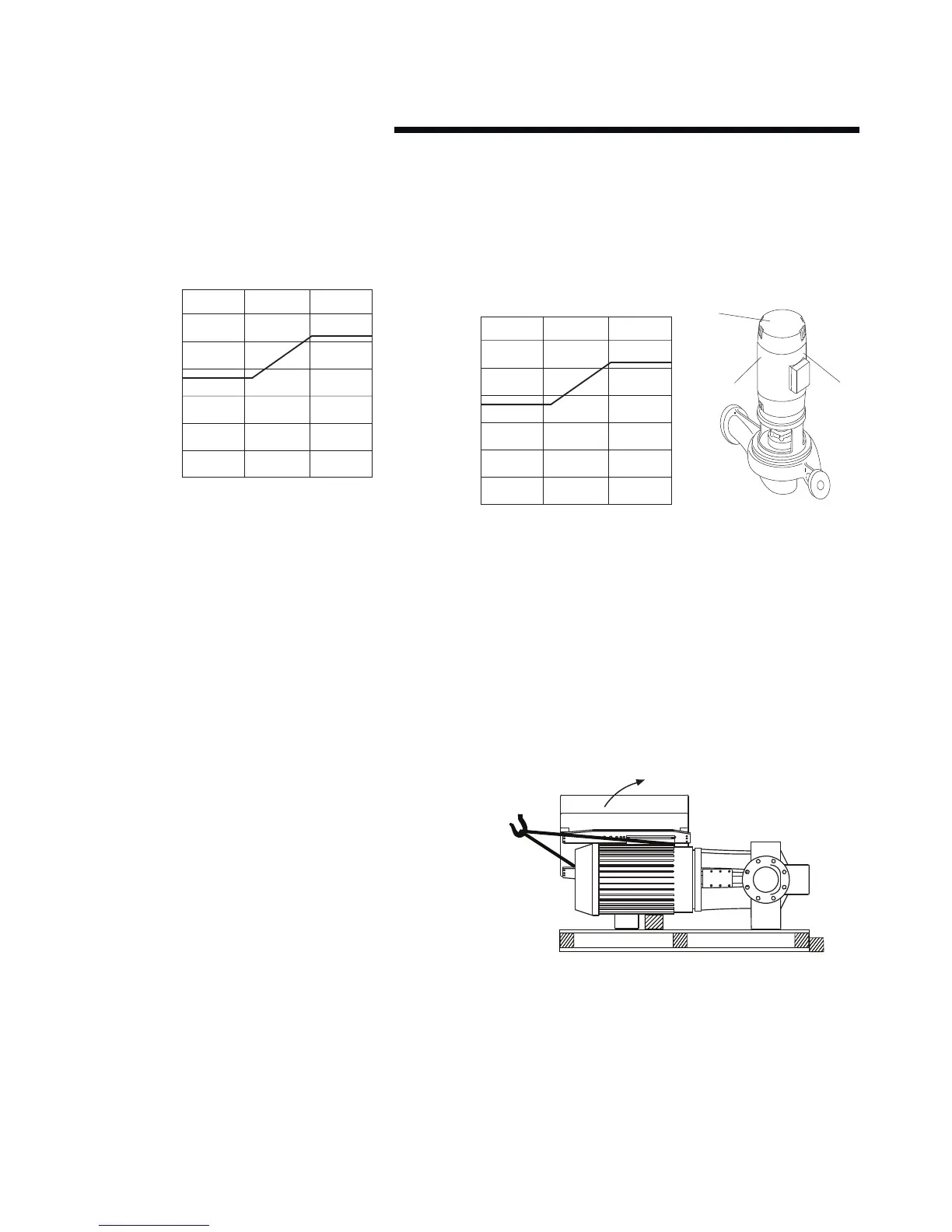
Armstrong Vertical In-Line pumps are designed to meet vibra-
tion levels set by Hydraulic Institute Standard hi Pump Vibration
9.6.4. Standard levels are as detailed below:
0.28
0.24
0.20
10 100 10001
0.16
0.12
0.08
0.04
0
input power @ test conditions–bhp
vibration – mm/sec rms, unfiltered
1.5 storage
Pumps not immediately placed into service, or removed from
service and stored, must be properly prepared to prevent exces-
sive rusting. Pump port protection plates must not be removed
until the pump is ready to connect to the piping.
Rotate the shaft periodically (at least monthly) to keep rotating
element free and bearings fully functional.
For long term storage (longer than three months), the pump
must be placed in a vertical position in a dry environment.
Internal rusting can be prevented by removing the plugs at the
top and bottom of the casing and drain or air blow out all water
to prevent rust buildup or the possibility of freezing. Be sure to
reinstall the plugs when the unit is made operational. Rustproof-
ing or packing the casing with moisture absorbing material and
covering the flanges is acceptable. When returning to service be
sure to remove the drying agent from the pump.
1.6 uncrating
Armstrong Vertical In-Line pumps are thoroughly inspected be-
fore shipment to assure they meet with your order requirements.
After removing the pump from the crate, make sure the equip-
ment is in good order and that all components are received as
called for on the packing list. Any shortages or damage should
be reported immediately. Use extreme care in handling the
unit, placing slings and hooks carefully so that stress will not be
imposed on the integrated controls, pump or motor. Never place
cable slings around the pump shaft or integrated controls. The
eye bolts or lifting lugs on the motor are intended for lifting only
the motor and not the complete unit.
1.7 handling design envelope 4300 & 4380 units
To handle Design Envelope 4300 and 4380 units from shipment,
secure the pallet following uncovering the unit, then placestraps
behind the integrated controls (around the motor feet) and
carefully lift the pumping unit to stand the pump vertically up-
right.Lift only suciently to remove the pallet, then lower onto a
flat surface. The pump and motor unit will free-stand on the cas-
ing ribs.Extra care is required to ensure the integrated controls
do not get damaged during lifting and installation.
For Design Envelope 4300 units, remove the coupling guard and
insert lifting straps through the pump/motor pedestal on either
side of the coupling. For Design Envelope 4380 units, remove
the motor eye-bolt and install a swivel hoist ring tied to a lifting
strap. Place secondary lifting straps around the motor feet (and/
or spacers). As the lifting device is engaged (Using a spacer bar
if necessary) and the straps tighten ensure no part of the strap-
ping is touching any part of the control or motor fan cover. Lift
the pumping unit carefully from the pallet in this manner and al-
low the unit to stand upright on a flat surface and re-position the
straps, if necessary, to ensure safe and damage-free transporta-
tion into the pipe installation.