24
7.2.1 setting parameters for constant
pressure control
• Parameter 716 - Enter the head (kPa) at design flow.
•
Parameter 717
- Enter the design flow (l/s).
•
Parameter 707
- Enter the minimum head requirement
(as a percentage of p716). which will be 100% for
constant pressure.
• Parameter 705 - Quadratic Head should be set to ’off’.
•
Parameter 798
- This is a calculated value from the
settings above and should not be changed.
7.3 proportional pressure control
Where a linear reduction in head is required with reducing flow
then the quadratic curve should be turned o.
7.3.1 setting parameters for
proportional pressure control
• Parameter 716 - Enter the head (kPa) at design flow.
•
Parameter 717
- Enter the design flow (l/s).
•
Parameter 707
- Enter the minimum head requirement
(as a percentage of p716).
• Parameter 705 - Quadratic Head should be set to ’off’.
•
Parameter 798
- This is a calculated value from the
settings above and should not be changed.
8.0 control using external feedback
(closed loop control).
Design Envelope pumps can be configured (using the keypad) to
accept a feedback signal from a remote sensor (e.g. temperature
transmitter for constant temperature). The connection of an
external device will depend on the device itself although typical
devices are 4-20mA, 2 wire where the supply will be provided by
24v dc on terminal 6 of x101 and the output signal connected to
terminal 1 of x101.
The parameter list following this section gives typical settings
for closed loop control.
8.1 parameter groups and descriptions.
group 0 – operation and display.
Language/Local Control – Parameters 001,002, 003
Not normally changed.
Active Set-up – Parameter 004
It is possible to program two separate sets of data for controlling
the inverter.
Program Set-up – Parameter 005
The active set-up can be either set-up 1, set-up 2 or can be
remotely switched between the two.
Copying of Set-ups – Parameter 006
A copy is made from the set-up selected in parameter 005
and copied to the set-up selected in parameter 006.
Copying of Set-ups Between Inverters – Parameter 007
• Connectkeypadtotheinverterfromwhichthedesired
set-up is to be copied.
• Select1inparameter007 to upload all parameters into the
key pad.
• Connectkeypadtotheinvertertowhichthedesiredset-up
is to be copied.
• Select3 in parameter 007 to download all parameters into
the inverter.
• Byselecting3 in parameter 007, copying from one size of
inverter to a dierent size will not aect the power settings.
Display Scaling – Parameter 008
Multiplication factor of frequency (normally set at 1).
Display Configuration – Parameters 009-012
Allows choice of data to displayed in lines 1 and 2 of the key pad.
Local Operations – Parameters 013 -019
Not normally changed.
group 1 – load and motor.
Configuration – Parameter 100
Sets the configuration under which the inverter is controlled.
attention:
Set to Process Closed Loop for control via the 4 -20mA trans-
ducer feedback input set to Speed Open Loop for Potentiometer,
bms or Sensorless control.
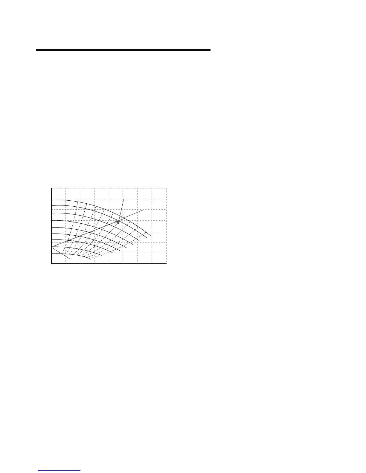
0
0
20
40
60
80
100
120
10
51
1450 rpm
1388 rpm
1290 rpm
1190 rpm
1090 rpm
990 rpm
894 rpm
750 rpm
580 rpm
62
71
77
81
82
81
77
1
2
3
4
5
6
7
71
20 30 40 50 60 70 80