19
Control key functions
[display / status] is used for selecting the mode of
display or for changing back to Display mode from
either the Quick menu mode or the Menu mode.
[quick menu] is used for programming the param-
eters that belong under the Quick menu mode. It
is possible to switch directly between Quick menu
mode and Menu mode.
[menu] is used for programming all parameters. It is
possible to switch directly between Menu mode and
Quick menu mode.
[change data] is used for changing the parameter
selected either in the Menu mode or the Quick
menu mode.
[cancel] is used if a change of the selected
parameter is not to be carried out.
[ok] is used for confirming a change of the
parameter selected.
[+/-] is used for selecting parameter and for
changing the chosen parameter or for changing the
read out in line 2.
[<>] is used for selecting group and to move the
cursor when changing numerical parameters.
[stop / reset] is used for stopping or for resetting
the pump after a drop-out (trip). Can be selected
via parameter 014 to be active or inactive. If stop is
activated, line 2 will flash, and [start] must
be activated.
attention:
Pressing [stop/reset] will prevent the pump from running also
with disconnected lcp. Restarting is only possible via the lcp
[start] key.
[jog] overrides the output frequency to a preset
frequency while the key is kept down. Can be
selected via parameter 015 to be active or inactive.
[fwd / rev] changes the direction of rotation of the
motor, which is indicated by means of the arrow on
the display although only in Local. This key is
inactive by default.
[start] is used for starting the pump after stop via
the [stop] key. Is always active, but cannot override
a stop command given via the terminal strip.
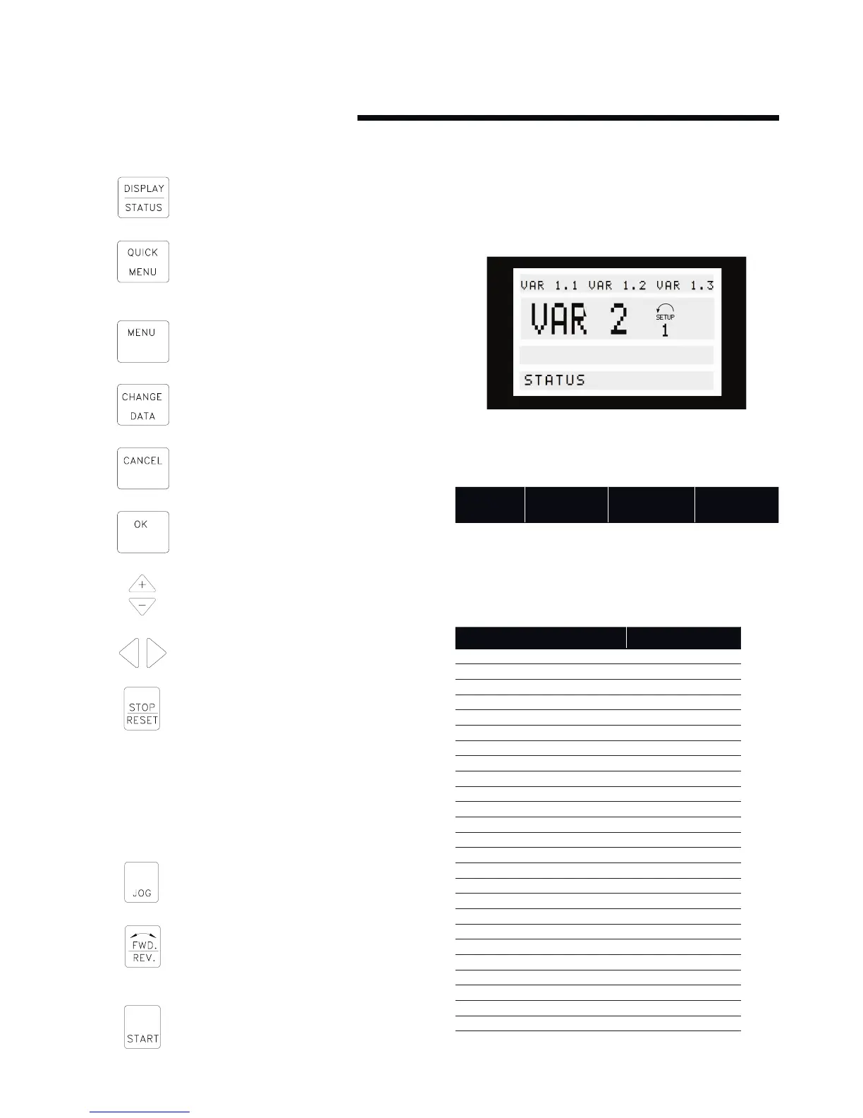
6.1.4 display mode
In normal operation, up to 4 dierent operating variables can be
indicated continuously: 1,1 and 1,2 and 1,3 and 2, and in line 4 the
present operating status or alarms and warnings that have arisen.
There are three options in connection with the choice of read
-out state in the Display mode - I, II and III. The choice of read-
out state determines the number of operating variables read out.
read-out
state:
i ii iii
Line 1 Description for
operating vari-
able in line 2
Data value for 3
operating vari-
ables in line 1
Description
for 3 operating
variables in line 1
The table below gives the units linked to the variables in the first
and second line of the display (see parameter 009).
operating variable unit
Reference [%]
Reference [unit]*
Feedback [unit]*
Frequency [Hz]
Frequency x scaling [-]
Motor current [A]
Torque [%]
Power [kW]
Power [HP]
Motor voltage [V]
dc-link voltage [V]
fc thermal [%]
Hours run [Hours]
Input status, dig. Input [Binary code]
External reference [%]
Status word [Hex]
Heat sink temp. [°c]
Alarm word [Hex]
Control word [Hex]
Warning word 1 [Hex]
Warning word 2 [Hex]
Analog input 1 [mA]
Analog input 2 [V]
Sensorless power [W]
Sensorless flow [l/s]
Sensorless head [kPa]
* Select in parameter 416. The unit is shown in readout
state 1 line 1 otherwise ’U’ is shown.