EasyManua.ls Logo

Armstrong 4300 - Page 36

Armstrong 4300
54 pages
Print Icon
To Next Page IconTo Next Page
To Previous Page IconTo Previous Page
Loading...
installation &
operating instructions
Design Envelope 4300 and 4380 vertical in-line
pumping unit with integrated controls
36
fig. 8 Relay connection terminals for c1 and c2 units
Page 12 of 26
The following illustrations identify the location of the relays within spec ic inverter sizes:
The illustrations in gures 6, 7 and 8 identify the locati on of the relays within specic inverter sizes:
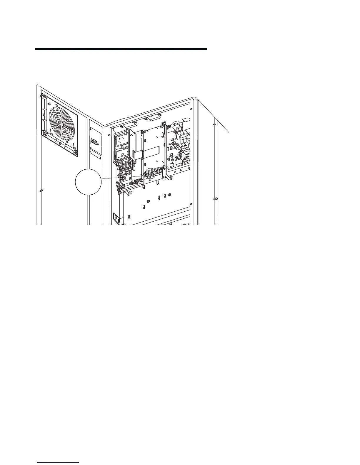
Figure 7. Relay Connection Terminals for C1 and C2 Units
Figure 6. Relay Connection Terminals for A5, B1 and
B2 Units
Figure 8. Relay Connection Terminals for D1 and D2 units
01 02 03
04 05 06
AUX RELAY

Table of Contents

Other manuals for Armstrong 4300

Related product manuals