2.2.3
Mounting Options
The NC4000 Node can be suspended from a horizontal cable (strand mount) or
mounted in an enclosure or equipment room (pedestal or surface mount).
See 4.1.1 Strand Mounting on page 4-1 for strand mounting procedures.
See 4.1.2 Pedestal or Surface Mounting on page 4-2 for pedestal/surface mounting
procedures.
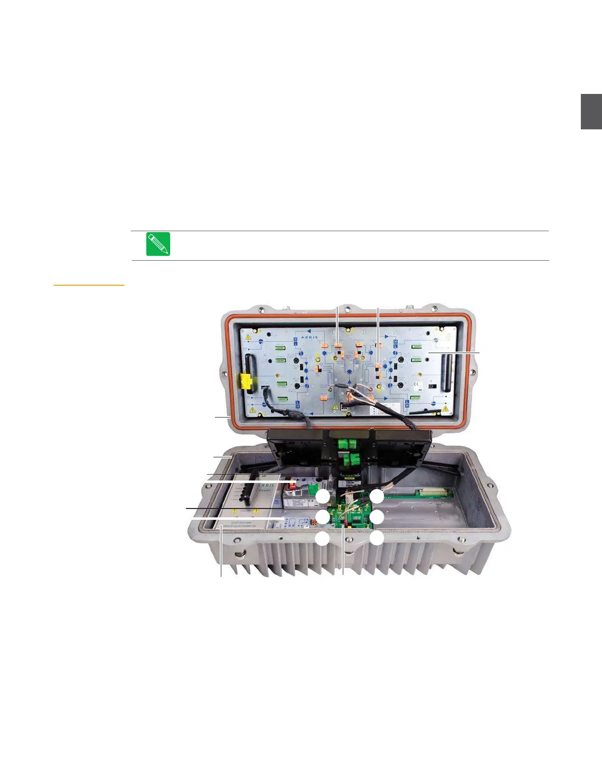
2.3
Component Layout
Figure 2.5 shows the NC4000 node opened. The RF amplifier tray (and associated equalizers,
pads, and fuses) is installed in the base. Power supplies and plug-in modules are installed in the
lid. The “A” through “F” callouts in Figure 2.5 indicate slot numbers on the lid motherboard.
Figure 2.5
is an example—specific NC4000 nodes can have different plug-in
modules.
Figure 2.5
NC4000 Node
Component Layout
Equalizers
Pads
RF amplifier tray
Base
Lid
Receiver
(forward path)
C D
Transceiver
(return path)
Power supply
2.3.1
RF Amplifier Tray
B E
A
F
Motherboard (lid)
The RF amplifier tray sends forward path RF to subscribers, and receives return path RF from
subscribers, through four coaxial ports (P1, P3, P4, and P6). The NC4000 node utilizes the
OA4324HG ultra high level RF output amplifier with GaN hybrids. The RF amplifier tray is easily
removed for access to the coaxial cable connectors under the tray (see
4.3 Removing and Replacing
the RF Amplifier Tray
on page 4-5). Foldout 1 at the back of this manual shows the RF amplifier in
detail.