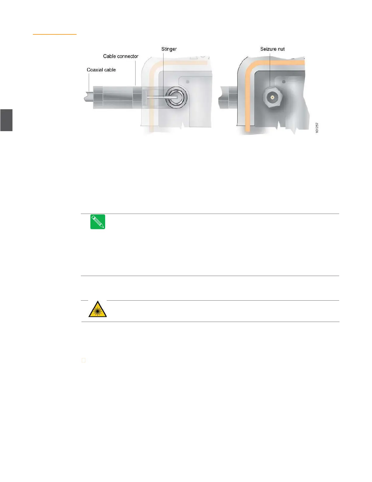
Figure 4.8
Coaxial Cable
Connections
4.5
Power Cable Connections
AC power can be brought in through any of the six ports on the base of the unit. Ports P2 and P5
are normally for AC power only. If you are connecting AC power through port P2 or P5, use the
procedures in 4.4 RF Coaxial Cable Connections on page 4-6 to install the power cable and attach it
via the seizure nut.
Torque power cable connectors to the connector manufacturer’s recommended torque.
Note
RF signals can also be routed over the cables attached to P2 and P5 for special
applications—contact ARRIS Field Services for information about routing RF through P2 and
P5.
Note
Special applications could include (1) forward loop for local signal injection (security
cameras) or (2) return path for back-hauling signals from the node to the headend (or hub).
Note
When routing RF over P2 or P5, connect the applicable RF cables (inside the node) to
the SMB connectors on the RF amplifier tray. These connectors are labeled A1 and A2 on
OA4324HG RF amplifiers.
4.6
Fiber Optic Cable Connections
DANGER
Laser Radiation
– Avoid any exposure to laser beams. Viewing the laser output with
certain optical instruments (e.g. eye loupes, magnifiers and microscopes) within a distance of
100 mm may pose an eye hazard.
Fiber optic cables are routed through the two ports on either end of the lid. You will have at least
one forward path (downstream) and one return path (upstream) fiber, more if the node is
segmented.
To install fiber service cables in the housing lid.
1.
Using a ½-inch wrench, remove the protective plug(s) from the fiber access port(s) on the
lid.
2.
Carefully pass the connector ends of the fiber optic service cable through this port. Insert
one fiber optic connector at a time. Be careful not to bend the fiber any more than is
necessary (Figure 4.9).
3.
Carefully thread the compression fitting into the port and torque the connectors to the
connector manufacturer’s recommended torque.