Figure 4.4
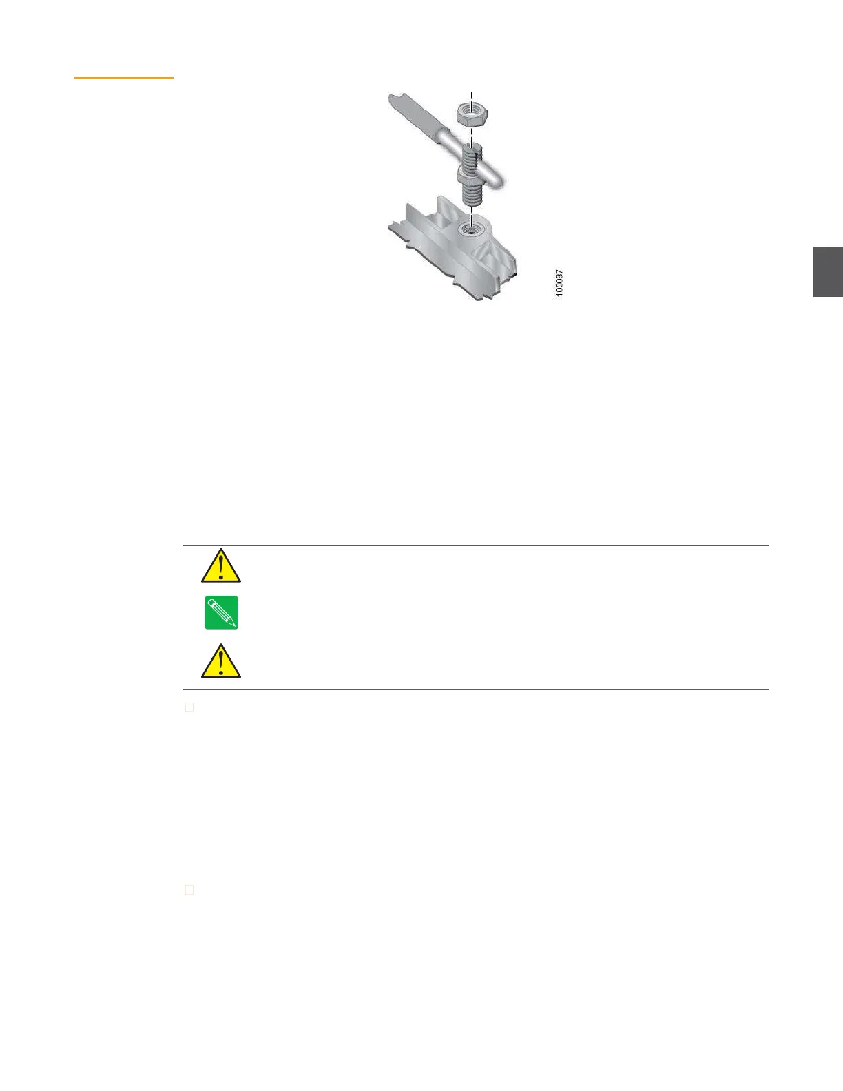
Grounding the
NC4000
4.2
Preconfiguration and Testing
NC4000 nodes should be preconfigured and tested in a shop/lab environment before being
installed in the network. The objective is to have fully functional and tested nodes that requires
only minimal adjustments during installation. See Chapter 3,
Configuring NC4000
Nodes for
shop/lab procedures.
4.3
Removing and Replacing the RF Amplifier Tray
The RF amplifier tray must be removed to make the RF coaxial cable connections (
4.4 RF Coaxial
Cable Connections on page 4-6) and power cable connections (4.5 Power Cable Connections on page
4-8). Perform steps 1 through 4 to remove the RF amplifier, and steps 5 through 7 to replace it after
the applicable cable connections have been made.
CAUTION
Do not remove the RF amplifier tray with cables attached to the lid motherboard.
Never allow the RF amplifier to hang from the lid motherboard by RF or power cables.
Note
If the RF amplifier tray is removed for any reason, re-torque the seizure nuts () to 6.25 foot-
pounds (8.5 newton-meters) before reinstalling it in the housing.
CAUTION
AC voltages in the range of 44 to 95 VAC can be present when power is connected
to the node. Shut down or disconnect external AC power to the node before removing or
replacing the RF amplifier tray in the base housing.
To remove the RF amplifier tray:
1.
Using a ½-inch wrench, loosen the eight housing bolts (Figure 4.21 on page 4-23) and swing
the lid away from the base.
2.
Disconnect all RF and power connections to the RF amplifier tray.
3.
Using a flat tip screwdriver, loosen the eight screws holding the RF amplifier tray in place
(Figure 4.5). (You can use a ¼-inch socket or nut driver if the RF amplifier tray fasteners
have a hex shank—part number 79-10339.)
4.
Carefully pull the RF amplifier tray out of the base.
To replace the RF amplifier tray.
1.
Orient the RF amplifier tray so that port P1 (upper right corner) lines up with port P1 in the
base. Gently push the RF amplifier into the base until it’s firmly seated.