Figure 4.14
RF Amplifier
OA4324HG—2x2
Segmentation
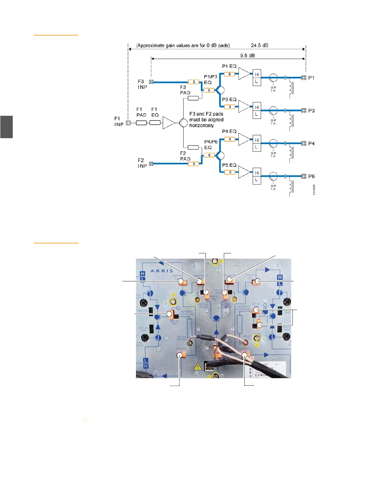
Figure 4.15
Figure 4.15 shows the pad and equalizer locations on the OA4324HG Optical Amplifier. This is the
configuration for one forward segment. For 2x2 segmentation the F2 and F3 input connectors must
have 0 dB pads in the horizontal position.
Pad and Equalizer
Locations
P4/P6 equalizer
F2 pad
F3 pad
P1/P3 equalizer
P6
equalizer
P1
equalizer
R2
pad
R1
pads
P4
equalizer
P3 equalizer
4.7.4
Forward Path RF Output and Slope Verification
To measure RF power output of the NC4000 node:
1.
Verify forward receiver RF output (input to the RF amplifier) as defined in
4.7.1 Forward
Path Receiver Setup on page 4-10 and Table 4.3 on page 4-12.