4.7
Forward Path Setup
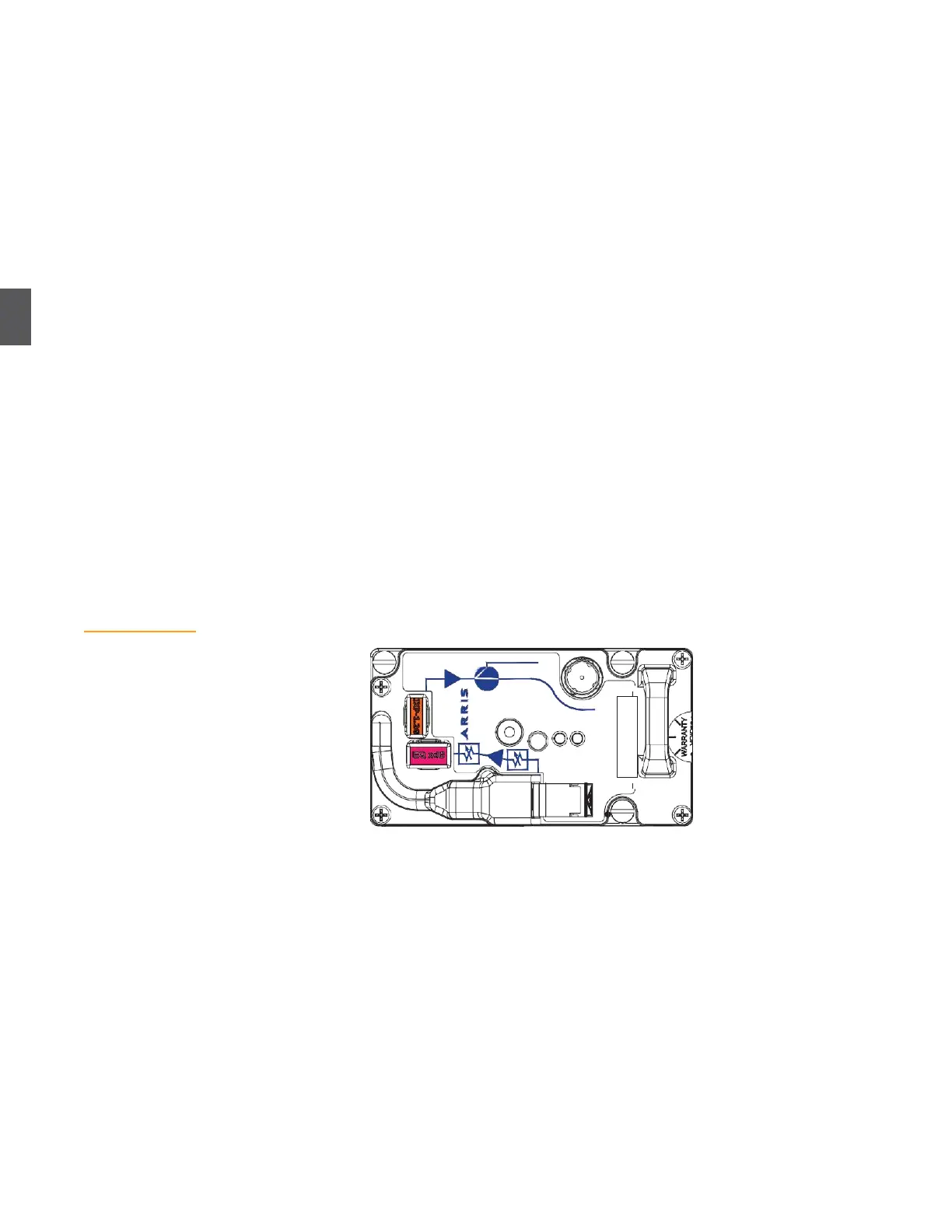
Figure 4.11
Forward Path
Receiver
There are four specific procedures to configure the forward path. Perform them in the order
shown.
Forward Path Receiver Setup (4.7.1 Forward Path Receiver Setup) verifies that the correct
number and type of forward receivers are installed, and that forward receiver RF output power
is within tolerance.
Forward Path RF Switching (4.7.2 Forward Path RF Switching on page 4-13) verifies that the
automatic RF switching module(s) are installed and configured correctly. (This is an optional
feature and may not be implemented.)
Forward Path Segmentation Setup (4.7.3 Forward Path Segmentation Setup on page 4-13)
verifies that the correct pads and equalizers are installed for the specific architecture and
segmentation scheme.
Forward Path RF Output and Slope Verification (4.7.4 Forward Path RF Output and Slope
Verification
on page 4-16) tells you how to measure RF output power (at low, medium, and high
frequency) and adjust pads and equalizers as necessary.
Measurements in 4.7.4 Forward Path RF Output and Slope Verification on page 4-16 may require you
to adjust pads and equalizers installed in 4.7.1 Forward Path Receiver Setup on page 4-10.
4.7.1
Forward Path Receiver Setup
This procedure assumes that the appropriate number and type of forward receivers are installed
per 3.4 Forward Path Configuration on page 3-7. Figure 4.11 shows an AR4x14G forward path
receiver. NC4000 nodes normally require one forward path receiver. (Two forward path receivers
are required to implement forward RF path switching, as described in
3.4.1 Automatic
Forward Path RF
Switching
on page 3-8.) Node management traffic is sent to the node through the receiver in
slot A. The
OPT. ALARM LED
is normally green, but switches to flashing green or red if
the
optical input is outside the operating range.
1.
Using an optical power meter, measure and record the input optical power level at the
fiber optic connector coming into the node. The acceptable range is –3 to +3 dBm when
using an AR4x03 and -8 to +2 dBm when using an AR4x14
2.
Verify that the AR4xxxG
ALARM
LED is lit.
If the
ALARM
LED is not lit, check (in the following order) 3.3 and 5 VDC power on the lid
motherboard test points, 3.3 and 5 VDC power at power supply test points, 44 to 95 VAC at the
power supply AC test point, applicable fuses, and the 44 to 95 VAC input to the node.
3.
Clean and install an SC/APC fiber jumper (JC-1112 or equivalent) from the optical input
connector on the receiver to the appropriate bulkhead connector in the fiber organizer
tray. (The JC-1112 fiber jumper is not included with the node and must be ordered and
purchased separately.)