Installing NC4000 Nodes 4-11
4.
Using a DVM (digital volt meter), measure and record the optical input power level at the
electrical test point (1V/mW) on the AR4xxxx receiver. Compare the optical power input
level to values shown in the following tables:
For one forward segment the OA42324HG RF amplifier requires an output of 36 dBmV at 1 GHz
for either the AR4x03G or AR4x14G receivers.
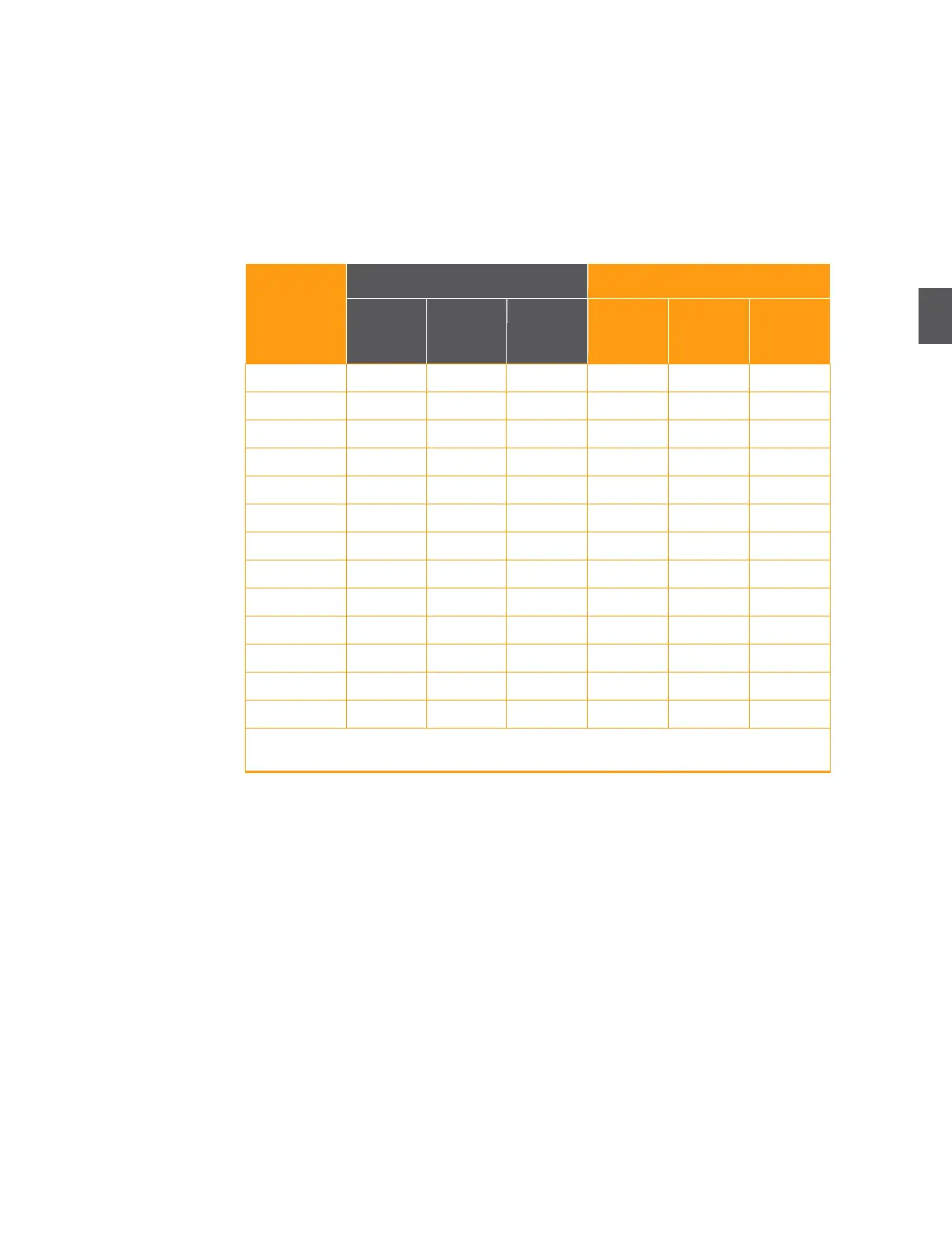
Use Table 4.1 for an AR4x03G receiver driving one forward segment into an OA4324HG RF
amplifier. Verify that the appropriate attenuation pad and equalizer are installed in the
AR4x03G receiver. Replace the pad and/or equalizer if required.
Table 4.1 AR4x03G Setup for One Forward Segment Into an OA4324HG
Optical Power
Input to Node
1V/mW
Test Point
(+/- 0.1V)
1V/mW
Test Point
(+/- 0.1V)
Note: Table 4.1 lists approximate values. Verify the RF output levels and adjust the pad and
equalizer values as necessary until they are within tolerance.
Use Table 4.2 for an AR4x14G receiver with ALC (automatic level control) driving one forward
segment into an OA4324HG RF amplifier.
An AR4x14G receiver is supplied with a 15 dB pad from the factory. ARRIS recommends setting
the ALC active before adjusting the 15 dB pad to avoid potentially damage from high RF levels.
Verify that the correct RF level and slope is achieved in the AR4x14G receiver. Replace the pad
and/or equalizer in the AR4x14G receiver if required