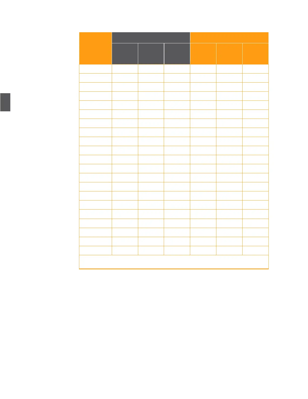
Table 4.2 AR4x14G Setup for One Forward Segment Into an OA4324HG
5.
Using a CATV Signal Level Meter, verify the RF output levels at the –20 dB test point on the
AR, as shown in Table 4.3. This assumes that the optical levels into the receivers are flat.
6.
If the levels at the –20 dB test point are not correct, adjust the pad and equalizer values as
necessary and repeat the previous step until they are within tolerance.
Optical Power
Input to Node
1V/mW
Test Point
(+/- 0.1V)
1V/mW
Test Point
(+/- 0.1V)
Note: Table 4.2 lists approximate values. Verify the RF output levels and adjust the pad and
equalizer values as necessary until they are within tolerance.