Installing NC4000 Nodes 4-19
Figure 4.17
RF Amplifier
4.8.2.1 Return Path Segmentation—OA4324HG RF Amplifiers
Return path segmentation with an OA4324HG RF amplifier is configured by three elements; (1) the
placement of R1 and R2 pads on the amplifier tray, (2) RF cabling between the RF amplifier tray and
the lid motherboard, and (3) plugging an RS4000 return path configuration module into the lid
motherboard.
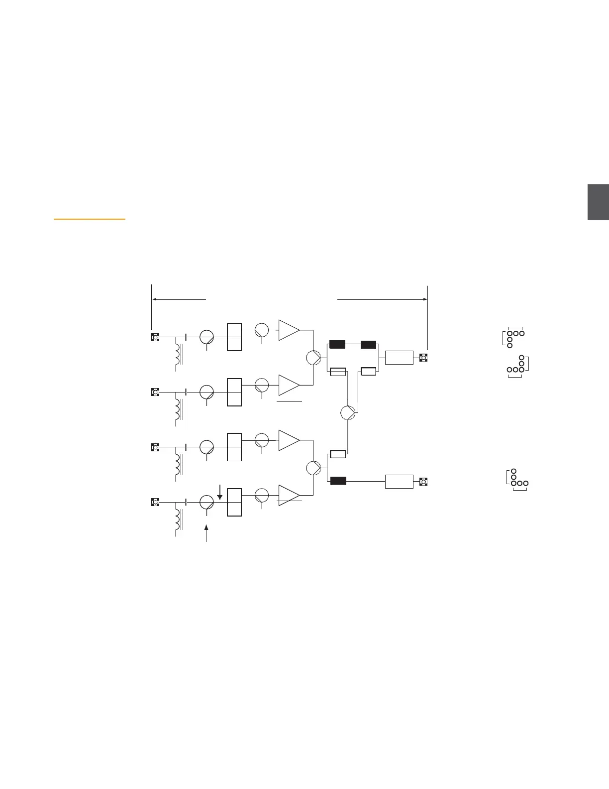
Figure 4.17 shows the OA4324HG return path schematic. Use the default pad values in the white
circles to configure one return segment (RF output at R1 OUT). Use the default pad values in the
black circles to configure two return segments (RF outputs at R1 OUT and R2 OUT).
Pad values may be different for some installations. The overall objective is to provide an RF input of
+8 dBmV (–60 dBmV/Hz) to the DT4xxx return path transceivers, as shown in Figure 4.18 on page
4-19. Use the procedures in
4.8.3 Return Path RF Verification
on page 4-21 to verify the RF return path
performance.
dBmV to dBmV/Hz equivalents
OA4324HG—Return
Segmentation
-56 dBmV/Hz
(+12 dBmV)
One segment
-3 dB loss with 6 dB pad
+3 dB gain with 0 dB pads
Two segments
-3 dB loss with 9 dB pads
+6 dB gain with 0 dB pads
shown for 6 MHz bandwidth signal
-59 dBmV/Hz
(+9 dBmV)
R1 Pad positions
2 seg
P1
L
H
O/P T.P.
I/P T.P.
9
0
R1 PAD
LF41xx
R1
OUT
1 seg
1 seg
P3
L
H
O/P T.P.
P4
L
H
O/P T.P.
I/P T.P.
I/P T.P.
0
0
R2 PAD
6
Use pad values in white
for one return segment
Use pad values in black
for two return segments
LF41xx
2 seg
R2 Pad positions
+12 dBmV
L
P6
H
9
I/P T.P.
R2
OUT
1 Seg
2 Seg
O/P T.P.
Inject a +32 dBmV test signal with a 6 MHz bandwidth at the applicable
test point to get +12 dBmV at the input to the lowpass filter