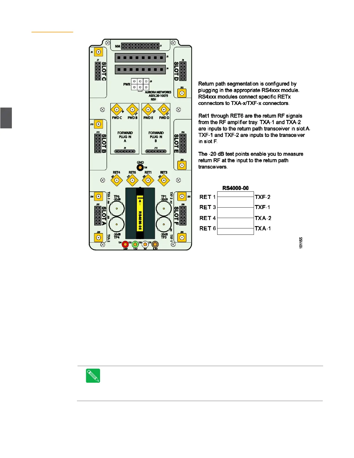
Figure 4.20
Lid Motherboard
With RS4000 Plug-in
4.8.3
Return Path RF Verification
This procedure injects an RF signal to verify the return path through the RF amplifier, and is
measured at the applicable test point on the lid motherboard, where the RF enters the transceiver
(see Figure 4.14 shows the forward path when using 2x2 segmentation with an AR4x24. The FWD F2 and
FWD F3 pads must be arranged horizontally using 0 dB pads to connect the FWD F2 and FWD F3 input
connectors (see Figure 4.15 for locations). Set the AR4x24G receiver to 18 dB slope with a 13 dB EQ in the
receiver (the AR has around 5 dB natural slope). An extra RF lead (PART NUMBER?) is required to connect
to the additional input. RF leads should connect to the F2 and F3 inputs. on page 4-15 for forward path
verification).
1.
Disconnect the downstream optical return cable (input) from the Rx connector on the
transceiver. Place a protective dust cover over the cable connector while it’s disconnected.
2.
Using a portable RF signal generator, inject a +32 dBmV CW carrier signal (6 MHz
bandwidth) into the applicable output test point. The test signal carrier can be at any
frequency as long as it is within the return path bandpass.
Note
Do not use the –20 dB input test points located on the amplifier assembly and
dedicated to testing the level of reverse signal; these test points are used for normal reverse
RF carrier measurements or reverse ingress troubleshooting and not for test signal injection.
Attempting to use these test points to inject signals will result in an improperly set-up or non-
functioning reverse path.