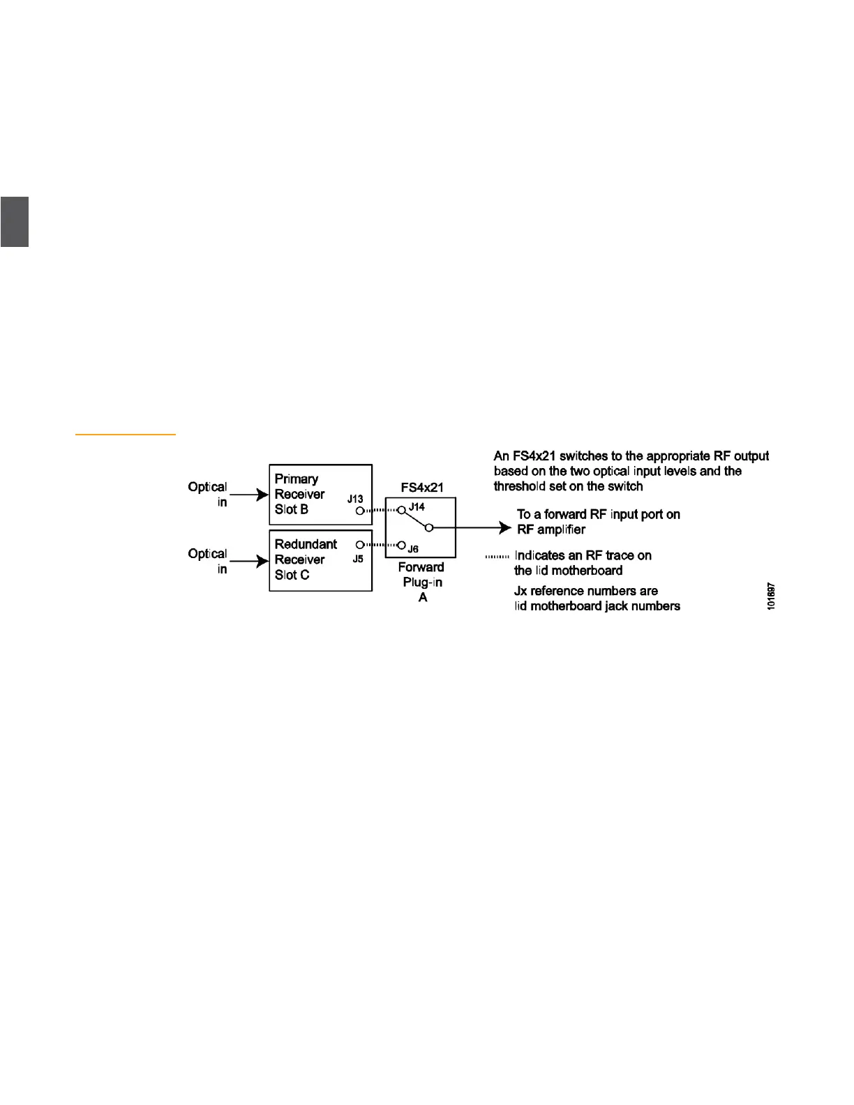
Figure 3.8
Forward Path RF
Switching
—
Functional Diagram
3.4.1
Automatic Forward Path RF Switching
NC4000 nodes can be configured for primary/redundant forward path RF switching. This is an
optional feature, and requires the installation of an FS4021 (AR4x03G only) or FS4121 (AR4x14G
and AR4x24G) switch on the lid motherboard. Figure 3.8 is a functional view of automatic forward
path RF switching.
Looking at Figure 3.8, we see that a single FS4x21 selects between the RF outputs of two forward
path receivers and switches that RF to an RF input port on the RF amplifier tray. The output of a
single FS4x21 provides the input to one forward segment.
The AR4xxxG receivers are designated “primary” and “redundant” based on their slot locations on
the lid motherboard. Both receivers are always on, but only one receiver RF output is selected. The
FS4x21 compares the optical input levels to the two receivers. If the optical input to the primary
receiver drops below a preset threshold compared to the optical input to the redundant receiver,
the FS4x21 automatically switches to the redundant receiver RF output. The FS4x21 will
automatically switch back to the primary receiver RF output when the fault causing the low optical
input to the primary receiver is corrected. The automatic switching threshold (–2, –4, –6, –7, –9, –12
or –13 dBm) is set by DIP switches on the underside of the FS4x21 per Table 3 FS4x21 Threshold
Setup. If the two optical inputs are within the threshold, the FS4x21 selects the primary receiver RF
output by default. The position of the FS4x21 switch(s) can be remotely controlled through ARRIS
Opti-Trace EMS (Element Management Software) enabling operators to test alternate routes and
redundant receivers.
For one forward segment using AR4x03G receivers, install a single FS4021 in forward plug-in
position A on the lid motherboard (see Figure 3.9), and install AR4x03G receivers in slots B and C.
For one forward segment using AR4x14G or AR4x24G receivers, install a single FS4121 in forward
plug-in position A on the lid motherboard, and install AR4x14G or AR4x24G receivers in slots B and
C.
Before installing an FS4x21 on the motherboard, set the switching threshold (see Table 3.3) using
the DIP switches on the underside of the FS4x21.