2.
Using a nut driver or ¼-inch socket (or flat tip screwdriver), start all eight screws, then
torque the screws to 15 inch-pounds (1.69 newton-meters) in the sequence shown in
Figure 4.5. Re-torque screws 1 through 8 a second time to compensate for any flexing of
the RF amplifier tray.
3.
Reconnect all RF and power connections to the RF amplifier.
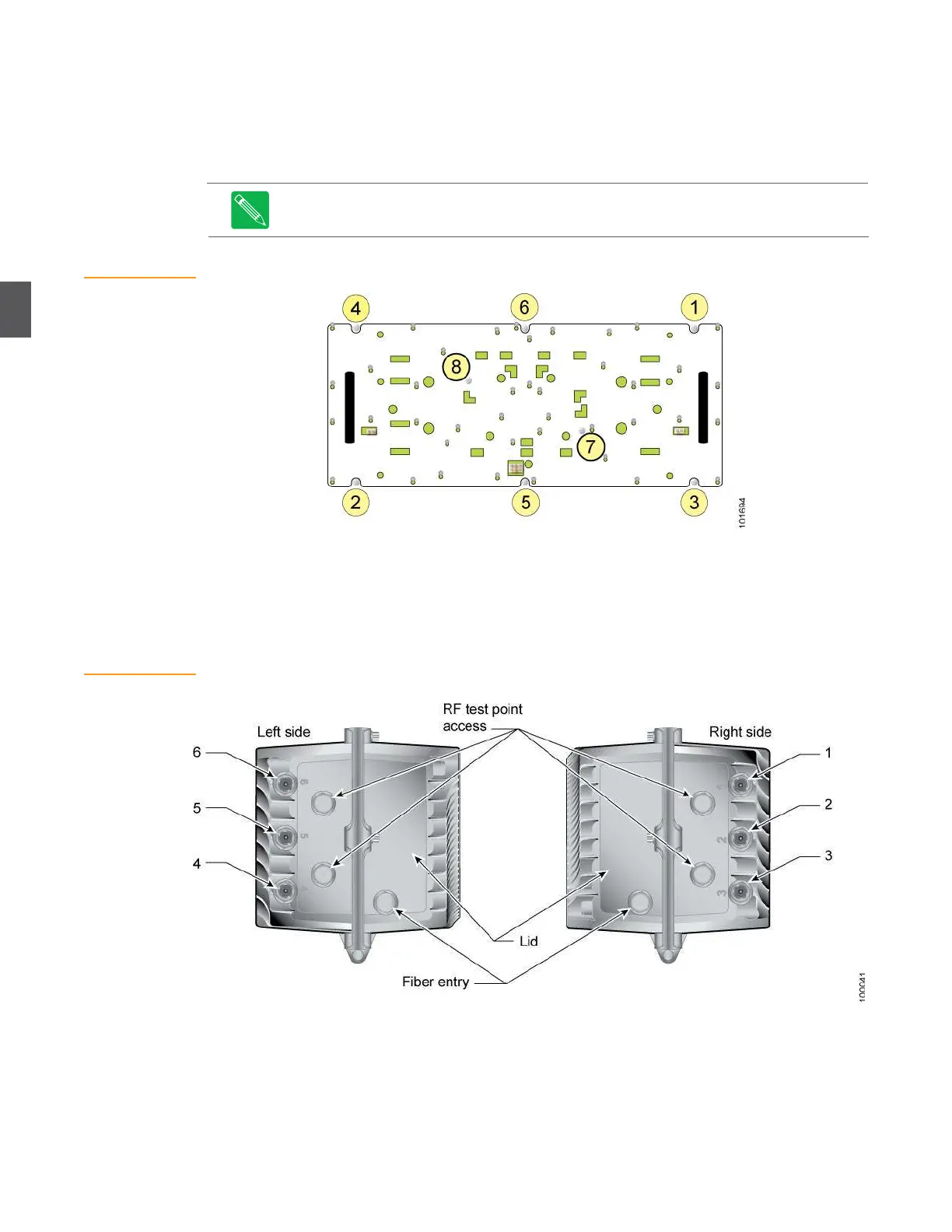
Note
Always tighten the screws holding the RF amplifier tray in the order shown in Figure 4.5
(the correct sequence is also marked on the cover tray). Failure to follow this sequence can result
in warping and misalignment.
Figure 4.5
RF Amplifier Tray—
Screw Tightening
Sequence
4.4
RF Coaxial Cable Connections
Figure 4.6
Port Locations
The four RF coaxial cable connections are through ports 1, 3, 4, and 6 on the base of the unit. These
ports provide forward (downstream) RF to subscribers, and accept return (upstream) RF from
subscribers for transmission back to the headend. Figure 4.6 shows the port locations.
Before opening the NC4000 housing, verify that all RF coaxial cables (up to four) are available at
the node location. Double-check cable labeling to ensure that cables get connected to the correct
ports. Inspect the RF cable connectors (KS type) and verify the length of the stinger (Figure 4.7). If
the connectors are not installed, install them now.