Table 3.2 PS4001 Power Supply Voltages
3.2.1
AC Power Distribution Fuses
AC power comes into an NC4000 through one of the six ports, and is distributed to the power
supply(s) through 90 V, 15 A, automotive blade fuses.
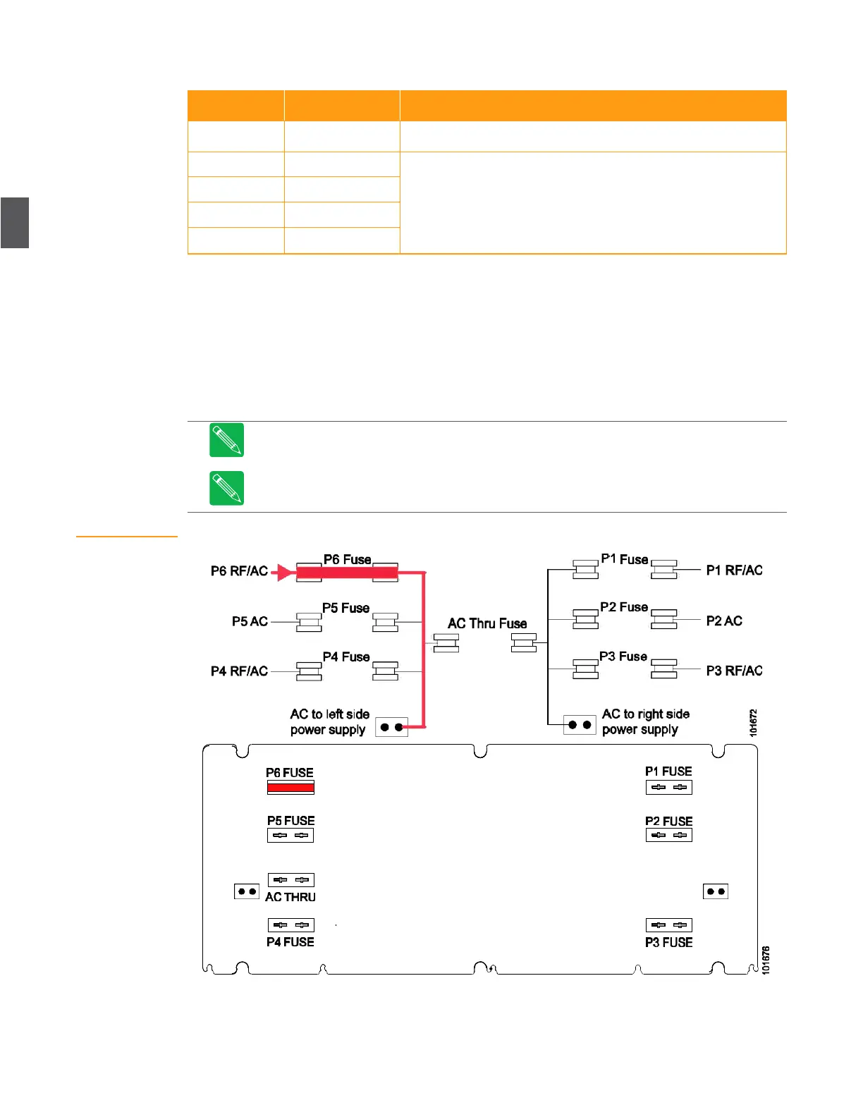
Figure 3.3 shows an example of AC power coming into P6, and routed to the power supply through
the P6 fuse. Looking at Figure 3.3, you can see that if AC power came in P5 you would place the fuse
in the P5 fuse holder, etc. While a single PS4001 power supply can power an NC4000 node, this
configuration doesn’t provide any redundancy.
Note
Use only 90 V, 15 A, automotive blade fuses (FZ2015-10 for a pack of ten) to avoid
damage to the unit.
Note
See Foldout 1 at the end of this manual for the actual fuse locations on the OA4324HG
RF amplifier tray.
Figure 3.3
Fuse Installation for
One Power Supply
Note: DC test points on the power supply are located before the ORing
diodes and are typically 0.2 to 0.3 Volts higher than the output
voltages. For actual buss voltages under load, measure DC voltages at
the test points on the lid motherboard ().