Installing NC4000 Nodes 4-17
2.
Using a CATV Signal Level Meter and test probe for GFA adaptors (TP4003), measure RF
output at the P1 test point. The acceptable RF levels are listed in Table 4.6 on page 4-16.
The measured RF levels should be within +/ 1 dB.
Note
Maximum output should not exceed 60 dBmV.
3.
If RF output levels or slope is out of tolerance, change pads and equalizers as necessary to
get the correct levels and slope.
4.
Repeat for P3, P4, and P6 test points.
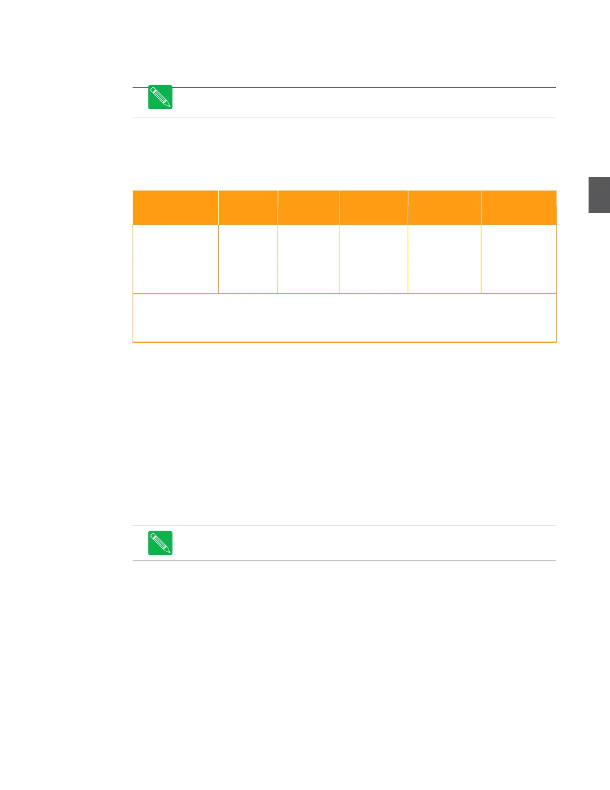
Table 4.6 OA4324HG RF Amplifier Output
OA4324HG with 18
dB slope, 1 GHz
OA4324HG with 18
dB slope, 870 MHz
(+42 dBmV)
+22 dBmV
(+42 dBmV)
(+42.2
dBmV)
+22.2 dBmV
(+42.2
dBmV)
(+49.7 dBmV)
+32.9 dBmV
(+52.9 dBmV)
+27.6 dBmV
(+57.6 dBmV)
+40 dBmV
(+60 dBmV)
Note 1: RF amplifier output levels are measured at the –20 dB test point. Levels in parentheses (…) are the true RF
amplifier output levels at P1, P3, P4, and P6.
Other slope and level options are available on request. Contact ARRIS Field services for options.
4.8
Return Path Setup
There are four specific procedures to configure the return path. Perform them in the order shown.
Return Path Transceiver Setup (4.8.1 Return Path Transceiver Setup on page 4-17) verifies the
correct number and type of return transceivers are installed.
Return Path Segmentation Setup (4.8.2 Return Path Segmentation Setup on page 4-17) verifies
the correct segmentation scheme.
Return Path RF Verification (4.8.3 Return Path RF Verification on page 4-21) verifies that the
four RF amplifier buses provide return RF signals to the return transceivers (via the
motherboard).
Return Path Transceiver Output Verification (4.8.4 Return Path Transceiver Output
Verification on page 4-22) verifies the optical output of each transceiver.
Note
Leave dust caps on optical ports and cable connectors until you are ready to connect
them. Clean all optical connectors before connecting cables to devices in the node.
Replace dust caps on optical ports and cable connectors after disconnecting them.
4.8.1
Return Path Transceiver Setup
This procedure assumes that the appropriate number and type of return path transceivers (one or
two) are installed per 3.5 Return Path Configuration on page 3-10. The transceiver in slot A is
required for node monitoring/management. See Chapter 5, Managing NC4000 Nodes for node
management details.
The input to the network optical RX port comes from the next downstream node or from the hub
or headend. Node management traffic comes in this port.
The output of the network optical TX port goes to the next upstream node or to the hub or
headend.