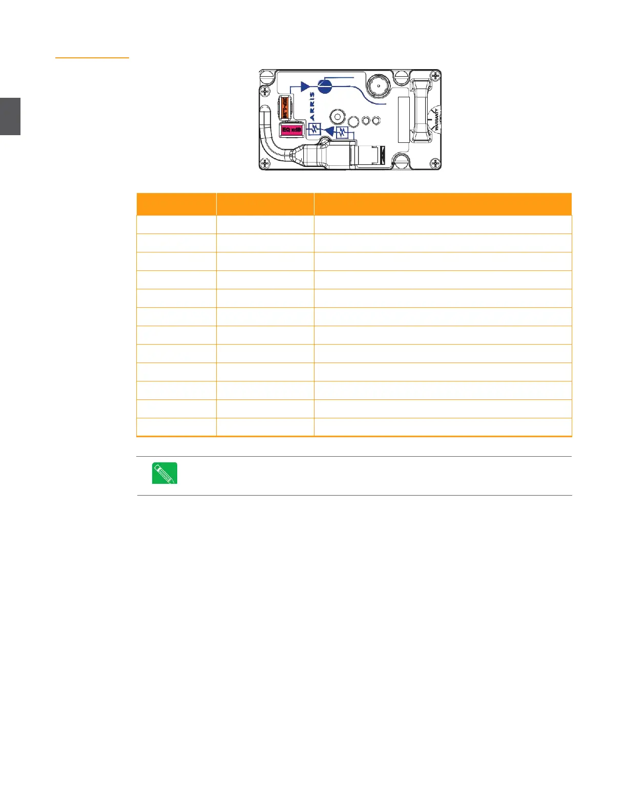
Figure 2.8
AR4x14G Forward
Path Receiver
Table 2.1 Forward Path Receivers
45/54 subsplit, 1 forward segment
45/54 subsplit, Hi Gain with 1 forward segment
45/54 subsplit, 2 forward segments
60/70 subsplit, 2x2 segmentable
65/85 subsplit , 2x2 segmentable
85/102 subsplit, 2x2 segmentable
Subsplit is in MHz and defines the upper end of the return RF and the lower end of the
forward RF. For example, a subsplit of 45/54 means return RF is 5 to 45 MHz and
forward RF is 54 to 870 or 1002 MHz.
2.3.5
Return Path Transceivers
Return path transceivers convert incoming RF from subscribers to optical output signals to be sent
to the headend (or hub). Figure 2.9 shows an example of a DT4250N Universal Digital Return Path
Transceiver. NC4000 nodes accommodate one or two DT4xxx transceivers. A single transceiver
will support one or two returns. A second transceiver would only be required for redundancy.
Table 2.2 lists the DT4xxx transceivers available for the NC4000. A transceiver is required in slot
A
of the lid motherboard for node monitoring/management. A second transceiver (when
applicable) goes in slot F. See
3.5 Return Path Configuration
on page 3-10 for return path transceiver
installation procedures.