Installing NC4000 Nodes 4-21
RS4xxx return path configuration modules plug into the lid motherboard (Figure 4.20 on page
4-21). Table 4.8 lists the available RS4xxx modules. Note that the RS4000 module can be ordered
with switches in each path. Switchable modules are designated by the suffix “SW.”
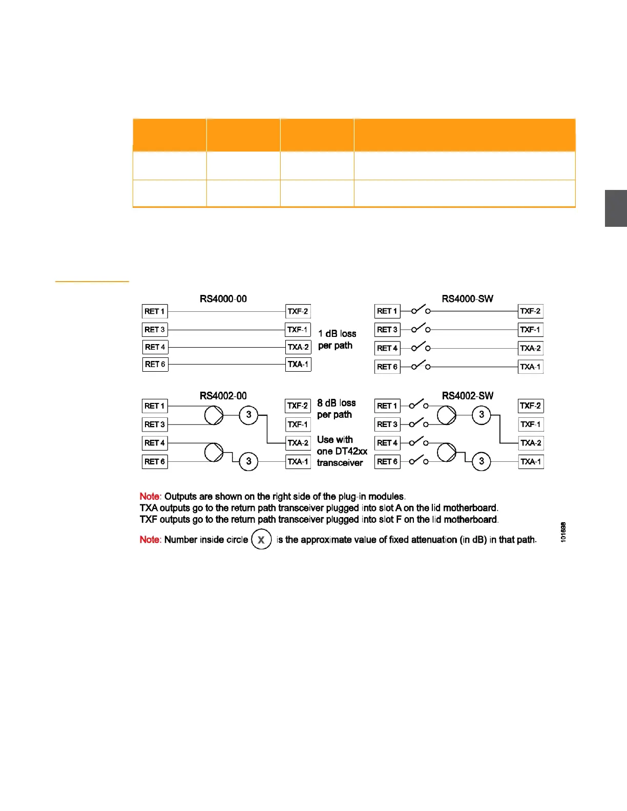
Figure 4.19shows the modules schematically.
Table 4.8 RS4xxx Return Path Configuration Modules
One or two transceivers (see Return Path Cabling—
OA4324HG RF Amplifier to Lid Motherboard).
Figure 4.19
RS4xxx Return Path
Configuration
Modules—
Schematics
The numbers in the circles (in Figure 4.19) represent the approximate value (in dB) for the fixed pad
in that path. Assume a 3.5 dB loss for 2:1 combiners/splitters. Loss per path (in dB) is shown below
each RS4xxx symbol. For example, the loss for any path through an RS4002 is 8 dB.