Figure 4.9
Fiber Optic Service
Cable
4.
Pull the fiber organizer tray (Figure 4.9) away from the lid and carefully spool the excess
fiber around the fiber hangers as many times as necessary to store the excess fiber. The
bend radius of the spool meets manufacturer specifications for fiber bend radius.
5.
Remove the protective boot from the fiber connector and clean the connector in
accordance with approved practices and materials. After cleaning, insert the connector
into the appropriate module.
Repeat for each forward path receiver and return path transceiver in the node.
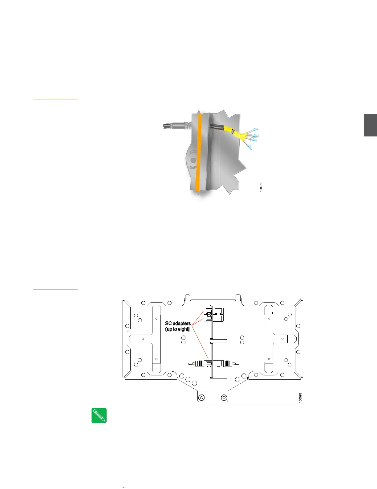
Figure 4.10
Fiber Tray
Be consistent when connecting fiber optics. Refer to the fiber design documentation to ensure the
proper color fiber is connected to the appropriate optical module. This will ensure easier service
and maintenance in the future. Connections from the service cable to plug-in receiver and
transceiver (or transponder) modules are described later in other sections of this document.
Figure 4.9 shows the underside of the fiber tray. Up to eight SC adapters can be installed in the
fiber tray. Service cable fibers (with SC/APC connectors) plug into one side of the adapters, and
fiber jumpers plug into the other side (of the adapters) and connect to optical ports on plug-in
modules in the node. Spool the extra fiber around the hangers at either end of the fiber tray. Fold
the fiber tray down into the housing lid when done.
Note
Leave dust caps on optical ports and cable connectors until you are ready to connect
them. Clean all optical connectors before connecting cables to devices in the node. Replace
dust caps on optical ports and cable connectors after disconnecting them.