Chapter 1 – Installation of the instrument
UM-23100B-U User manual ATEQ F CLASS Page 13/90
2.2.1. 3) J3 Connector (I/O inputs/outputs) programmable input
Input 7 (pin 9) can be parameterised in the CONFIGURATION/PROGRAMM INPUT
menu.
The programmable functions available on this input are all the specials cycle:
9 Program selection.
9 Regulator 1 adjust request.
9 Infinite fill request.
9 Auto zero piezzo request.
9 Calibration learn request.
9 Calibration check request.
9 ATR learn request.
9 Volume calculation request.
Some possibilities appear only if the function is used.
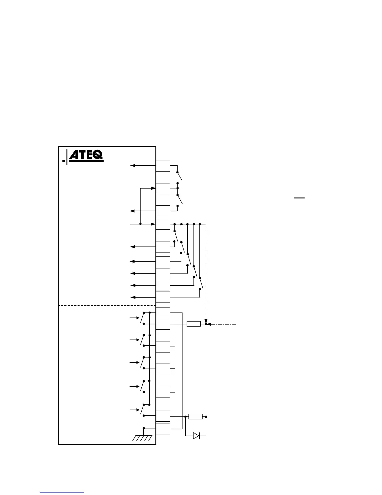
2.2.1. 4) J3 Connector (I/O inputs/outputs) drawing
I
1
(Reset)
Customer
16 programs
input board
I
2
(Start)
I
3
(Pr 1 + 1)
I
4
(Pr 2 + 1)
Good part output
Com.
O
1
Fail test part output
O
2
O
3
Fail reference
part output
O
4
Alarm
O
5
End of cycle
24 V DC 0,3 A max
ATEQ
24 V DC
0,3 A max
internal supply
I
6
(Pr 8 + 1)
I
5
(Pr 4 + 1)
I
7
(Programmable input)
16
15
14
13
12
11
10
9
8
7
6
5
4
3
2
1
0,2 A max
0,2 A max
Load
Load
Masse / Ground
Option
24 V DC
Customer
external
supply
Note: The 24V power
supply must be
provided by the internal
power supply of the
ATEQ instrument (0,3A
maximum) OR through
an external power
supply provided by the
customer.
 Loading...