Chapter 1 – Installation of the instrument
UM-23100B-U User manual ATEQ F CLASS Page 12/90
2.2. CONNECTOR DETAILS
2.2.1. Electrical connectors
The ATEQ F CLASS operate on a voltage of 24V DC either:
9 using the 24V DC transformer supplied with the instrument,
9 or via the networking cable when the instrument is a slave.
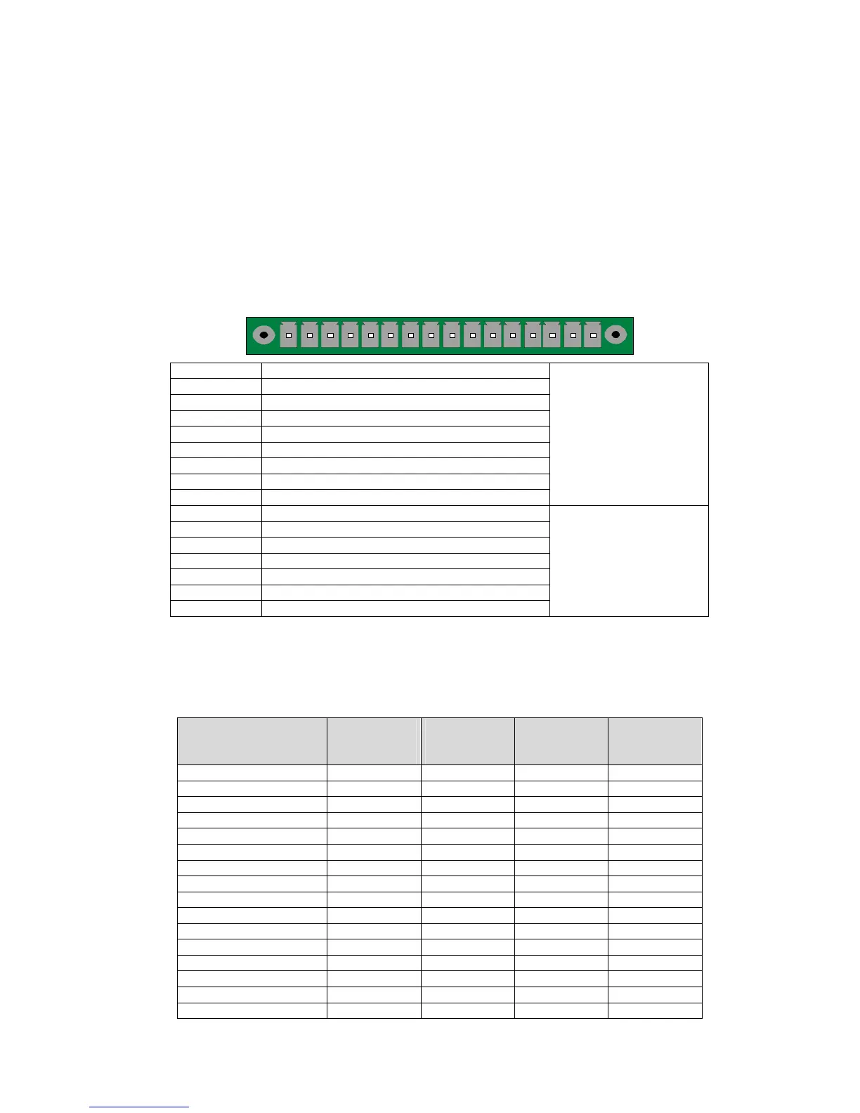
2.2.1. 1) J3 Connector (I/O inputs/outputs)
1 2 3 4 5 6 7 8 9 10111213141516
PIN 1 Reset (input 1)
PIN 2 Common (+ 24 V DC)
PIN 3 START (input 2)
PIN 4 Common (+ 24 V DC)
PIN 5 Input 3 (program selection)
PIN 6 Input 4 (program selection)
PIN 7 Input 5 (program selection)
PIN 8 Input 6 (program selection)
PIN 9 Input 7 (programmable input)
INPUTS
(activation by 24 V DC)
PIN 10 Common
PIN 11 Part OK output
PIN 12 Test part default output
PIN 13 Reference part default output
PIN 14 Warning output
PIN 15 Cycle end output
PIN 16 0 V
DRY CONTACT
OUTPUT
60V AC / DC Max
200mA Max
2.2.1. 2) Activating a program from the J3 connector inputs
To activate a program from the J3 connector inputs, you have to select pins 5 to 9 (one
or more). Binary weight n + 1.
Pin combinations for program selection
Program
number
Pin 5
(Input 3)
Pin 6
(Input 4)
Pin 7
(Input 5)
Pin 8
(Input 6)
1 0 0 0 0
2 1 0 0 0
3 0 1 0 0
4 1 1 0 0
5 0 0 1 0
6 1 0 1 0
7 0 1 1 0
8 1 1 1 0
9 0 0 0 1
10 1 0 0 1
11 0 1 0 1
12 1 1 0 1
13 0 0 1 1
14 1 0 1 1
15 0 1 1 1
16 1 1 1 1
 Loading...