Sheet # 692/1u – Electric connectors (F610)
Version 1.04a User guide ATEQ 6th series Page 4/7
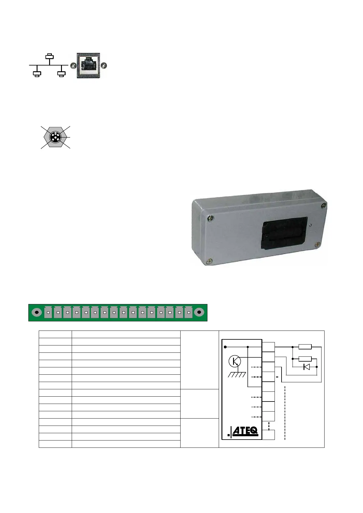
3.3.5. Input and output Ethernet/IP
Standard connection Ethernet TCP / IP protocol.
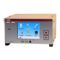
3.4. ANALOG OUTPUTS (OPTION)
This option is not possible if Devicenet or Profinet options are installed.
Connection for analog outputs.
2 1
4
3
5
¾ Pin 1: sensor 1 (plus).
¾ Pin 2: sensor 1 (minus).
¾ Pin 3: sensor 2 (plus).
¾ Pin 4: sensor 2 (minus).
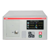
4. OTHERS CONNECTORS
The following connectors are located under
the gland cap:
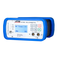
4.1. CONNECTOR CODES 6OUTPUT /6 INPUTS (OPTION)
12345678910111213141516
Output / inputs codes.
Pin 1 COMMUN (Outputs 1, 2, 3) + 24 V DC
Pin 2 Output n°1, open collector
Pin 3 Output n°2, open collector
Pin 4 Output n°3, open collector
Pin 5 COMMON (Outputs 4, 5, 6) + 24 V DC
Pin 6 Output n°4, open collector
Pin 7 Output n°5, open collector
Pin 8 Output n°6, open collector
Output
codes
24V DC
100mA Max
Pin 9 Input 0 (NPN or PNP)*
Pin 10 Input 1 (NPN or PNP)*
Pin 11 Input 2 (NPN or PNP)*
Pin 12 Input 3 (NPN or PNP)*
Inputs
Pin 13 Input 4 (NPN or PNP)*
Pin 14 Ground
Pin 15 Input 5 (NPN or PNP)*
Pin 16 Ground
Analogue
outputs
24 V DC
8
7
6
5
4
3
2
1
0,1 A max
Charge / Load
Obligatory
diode for an
inductive load.
* Inputs NPN or PNP following the strap position on the board.